
Wire Bending and Continuous Line Drawing
Loading the math board and drawing, please wait…
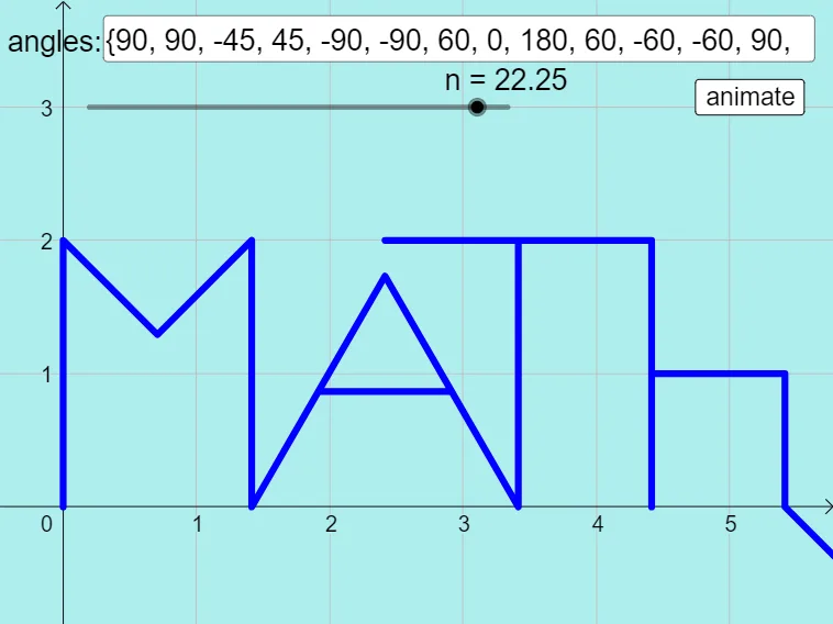
This example demonstrates how to dynamically draw a bent wire shape based on user-entered angles. It involves core math concepts like angles, coordinates, 3D vectors, linear equations, Pythagorean theorem, and sine functions. Construction highlights include GeoGebra commands like Append, Length, Sequence, Take, PolyLine, Textfield, and Corner. Suitable for high school and above learners exploring spatial geometry and parametric drawing.
GeoGebra Commands & Parameters
Append(0, l1) → l1appendLength(l1) → lenSequence(If[n ≥ t, Element[l1, t], anglepartial], t, 1, len) → l1inprogressSequence(cos(Element[l1inprogress, t]°), t, 1, len) → l1xTake(l1, 1, 3) → l2Sequence(sin(Element[l1inprogress, t]°), t, 1, len) → l1yAppend((0, 0), Sequence[(Sum[Take[l1x, 1, t]], Sum[Take[l1y, 1, t]]), t, 1, len]) → PointsPolyLine(Points) → polyTextfield(l1) → InputBox1Corner(5) → dims
AI Drawing Prompt Reference
Draw a bent wire shape based on user-entered angles. First, input a series of angles, then calculate the x and y coordinates based on these angles. Next, use these coordinates to draw a continuous line. Finally, display the list of input angles and mark the starting point of the line.
The prompt above was compiled from the original drawing commands and is for reference only.