
PP Dissection Method Demonstration
Loading the math board and drawing, please wait…
In collections
Cutting up squares
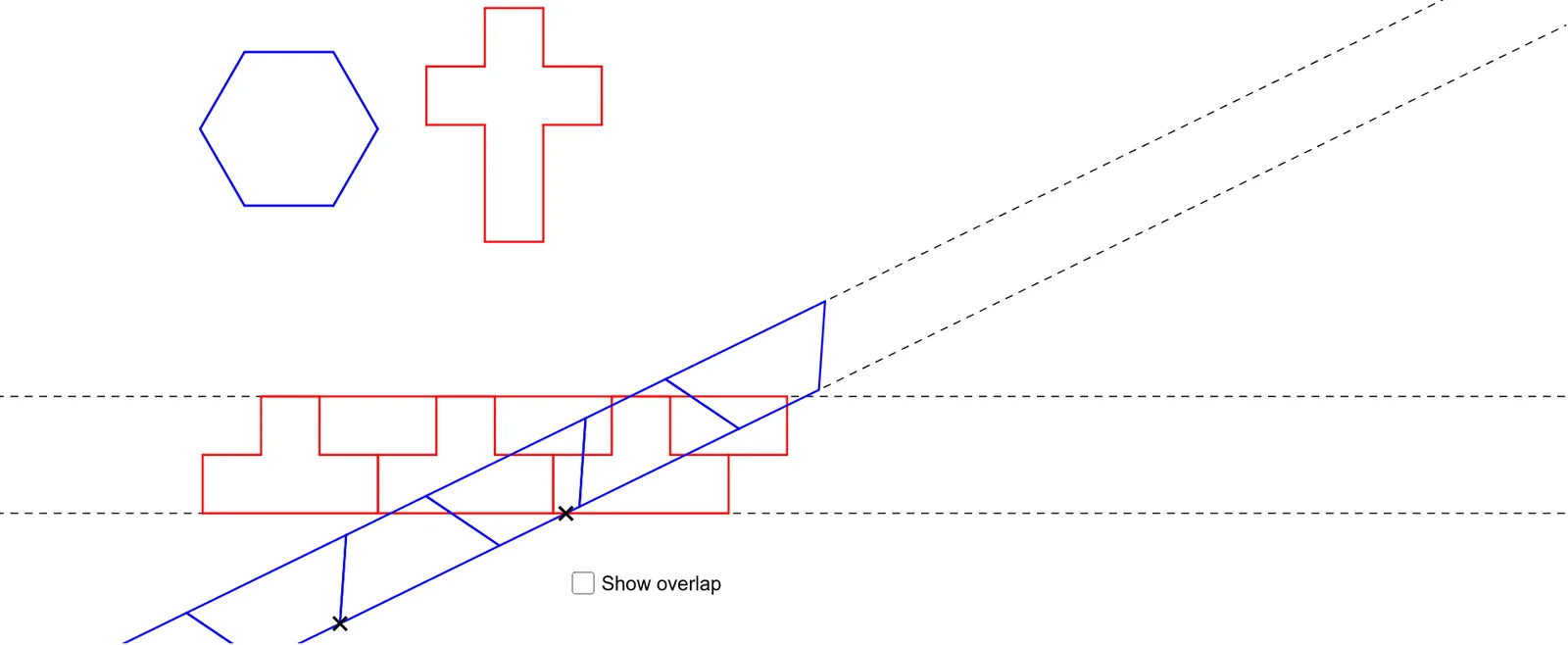
This example demonstrates the geometric construction process of the PP dissection method through dynamic visualization of shape transformations and combinations. It involves core mathematical concepts such as Similarity Transformation, Combinatorics, Indefinite Integral, Function Graph, and Multiplication. The construction highlights GeoGebra commands like Circle, Line, Intersect, Polygon, OrthogonalLine, Point, Vector, Translate, Segment, Midpoint, and Rotate. Suitable for high school and above, it provides an intuitive representation of complex geometric transformations and integral operations.
GeoGebra Commands & Parameters
Circle(A, 1) → cLine(A, B) → aIntersect(c, a, 2) → CPolygon(A, C, 3) → poly1, d, a_1, c_1, DPolygon(C, D, 6) → poly2, c_2, H, d_1, b, e, f, g, E, F, GCircle(I, 0.6580370064762462) → hOrthogonalLine(I, d_1) → iOrthogonalLine(I, i) → jIntersect(h, i, 1) → JPolygon(J, I, 4) → poly3, j_1, i_1, k, l, K, LPolygon(K, I, 4) → poly4, k_1, i_2, m, n, M, NPolygon(N, M, 4) → poly5, n_1, m_1, p, q, O, PPolygon(P, O, 4) → poly6, p_1, o, r, s, Q, RPolygon(M, I, 4) → poly7, m_2, i_3, t, b_1, S, TPolygon(K, N, 4) → poly8, k_2, n_2, e_1, f_1, U, VPolygon(J, L, S, I, K, V, U, N, R, Q, M, T) → poly9, j_2, t_1, s_1, i_4, l_1, k_3, v, u, n_3, r_1, q_1, m_3Line(W, Z) → g_1Circle(W, (2 * side)) → h_1OrthogonalLine(W, g_1) → a_2Intersect(h_1, a_2, 1) → A_1OrthogonalLine(A_1, a_2) → b_2Point(b_2) → B_1Polygon(T, U, V, K, L, J, I, S) → poly10, t_2, u_1, v_1, k_4, l_2, j_3, i_5, s_2Vector(T, B_1) → wTranslate(T, w) → T'Translate(U, w) → U'Translate(V, w) → V'Translate(K, w) → K'Translate(L, w) → L'Translate(J, w) → J'Translate(I, w) → I'Translate(S, w) → S'Polygon(T', U', V', K', L', J', I', S') → poly10', t', u', v', k', l', j', i', s'Vector(B_1, U') → zTranslate(T', z) → T''Translate(U', z) → U''Translate(V', z) → V''Translate(K', z) → K''Translate(L', z) → L''Translate(J', z) → J''Translate(I', z) → I''Translate(S', z) → S''Polygon(T'', U'', V'', K'', L'', J'', I'', S'') → poly10'', t'', u'', v'', k'', l'', j'', i'', s''Translate(T'', z) → T'''Translate(U'', z) → U'''Translate(V'', z) → V'''Translate(K'', z) → K'''Translate(L'', z) → L'''Translate(J'', z) → J'''Translate(I'', z) → I'''Translate(S'', z) → S'''Polygon(T''', U''', V''', K''', L''', J''', I''', S''') → poly10''', t''', u''', v''', k''', l''', j''', i''', s'''Translate(T''', z) → C_1Translate(U''', z) → D_1Translate(V''', z) → E_1Translate(K''', z) → F_1Translate(L''', z) → G_1Translate(J''', z) → H_1Translate(I''', z) → I_1Translate(S''', z) → J_1Polygon(C_1, D_1, E_1, F_1, G_1, H_1, I_1, J_1) → poly11, c_3, d_2, e_2, f_2, g_2, h_2, i_6, j_4Segment(J', G_1) → p_2Segment(V''', I_1) → q_2Segment(I_1, H_1) → r_2Segment(J', H_1) → a_3Point(b_2) → K_1Circle(K_1, 3) → d_3Intersect(d_3, g_1, 2) → L_1Line(K_1, L_1) → b_3Circle(K_1, 0.8660254037844386) → e_3OrthogonalLine(K_1, b_3) → f_3Intersect(e_3, f_3, 2) → M_1Line(M_1, b_3) → g_3Circle(K_1, 1) → h_3Circle(K_1, 2) → p_3Point(b_3) → N_1Circle(N_1, 1) → q_3Circle(N_1, 2) → r_3Intersect(r_3, b_3, 2) → O_1Intersect(q_3, g_3, 2) → P_1Circle(O_1, 1) → s_3Intersect(s_3, g_3, 1) → Q_1Polygon(N_1, P_1, Q_1, O_1) → poly12, n_4, p_4, q_4, o_1Midpoint(q_4) → R_1Rotate(N_1, 180°, R_1) → S_1Rotate(P_1, 180°, R_1) → T_1Rotate(Q_1, 180°, R_1) → U_1Rotate(O_1, 180°, R_1) → V_1Polygon(S_1, T_1, U_1, V_1) → poly12', s_4, t_3, u_2, v_2Midpoint(n_4) → W_1Midpoint(s_4) → Z_1Rotate(N_1, 180°, W_1) → A_2Rotate(P_1, 180°, W_1) → B_2Rotate(Q_1, 180°, W_1) → C_2Rotate(O_1, 180°, W_1) → D_2Polygon(A_2, B_2, C_2, D_2) → poly12'_1, a_4, b_4, c_4, d_4Rotate(S_1, 180°, Z_1) → E_2Rotate(T_1, 180°, Z_1) → F_2Rotate(U_1, 180°, Z_1) → G_2Rotate(V_1, 180°, Z_1) → H_2Polygon(E_2, F_2, G_2, H_2) → poly12'', e_4, f_4, g_4, h_4Midpoint(c_4) → I_2Midpoint(g_4) → J_2Rotate(E_2, 180°, J_2) → K_2Rotate(F_2, 180°, J_2) → L_2Rotate(G_2, 180°, J_2) → M_2Rotate(H_2, 180°, J_2) → N_2Polygon(K_2, L_2, M_2, N_2) → poly12''', k_5, l_3, m_4, n_5Rotate(A_2, 180°, I_2) → O_2Rotate(B_2, 180°, I_2) → P_2Rotate(C_2, 180°, I_2) → Q_2Rotate(D_2, 180°, I_2) → R_2Polygon(O_2, P_2, Q_2, R_2) → poly13, o_2, p_5, q_5, r_4Intersect(b_2, g_3) → S_2Intersect(g_1, g_3) → T_2Intersect(b_3, g_1) → U_2Polygon(K_1, S_2, T_2, U_2) → q1, l_4, t_4, f_5, g_5
AI Drawing Prompt Reference
Visualize the dynamic transformation process of a geometric figure, starting with a circle and a line segment, constructing two polygons through their intersection points, then using similarity transformations and orthogonal lines to build multiple small quadrilaterals, combining these to form a complex shape, and finally demonstrating the symmetry and combination relationships of the figure through translation operations, embodying concepts of geometric construction, transformation, and integral operations.
The prompt above was compiled from the original drawing commands and is for reference only.