
Isometric Projection: 3D to 2D Geometric Transformation Demo
Loading the math board and drawing, please wait…
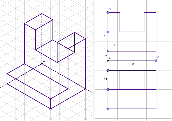
This example demonstrates isometric projection, converting 3D solid shapes into 2D plane views. Core concepts include solid geometry, projection transformations, and spatial coordinate systems. Construction utilizes GeoGebra commands like Point, Line, Ray, Segment, Circle, Midpoint, and Intersect to establish geometric relationships. Suitable for high school or university geometry courses, aiding in understanding spatial visualization and technical drawing skills.
GeoGebra Commands & Parameters
Point(a_3) → COrthogonalLine(A, a_3) → bPoint(b) → FLine(F, a_3) → cLine(C, b) → d_1Intersect(c, d_1) → GPoint(b) → BPoint(b) → JRay(A, D) → eRay(A, C_1) → fRay(A, B_1) → gSegment(A, C) → wCircle(A, w) → h_1Intersect(h_1, g) → C_a,Segment(B, A) → hCircle(A, h) → kIntersect(k, e, 1) → B_aLine(C_a, e) → iLine(B_a, g) → jLine(C_a, f) → lSegment(F, J) → dCircle(A, d) → pIntersect(p, f, 1) → A_2Line(A_2, g) → mIntersect(l, m) → ELine(B_a, f) → nLine(A_2, e) → qIntersect(i, j) → HPoint(h) → OSegment(A, O) → h1Circle(A, h1) → sIntersect(s, e, 1) → PLine(P, g) → tLine(O, w) → a_1Segment(F, G) → e_1Midpoint(B_a, H) → UMidpoint(B_a, U) → VMidpoint(U, H) → WLine(V, e) → j_1Line(W, e) → k_1Intersect(t, j_1) → ZIntersect(t, k_1) → A_1Segment(V, Z) → l_1Segment(Z, A_1) → m_1Segment(A_1, W) → n_1Point(d) → D_1Line(D_1, e_1) → p_1Intersect(d_1, p_1) → G_1Segment(F, D_1) → d1Circle(B_a, d1) → q_1Intersect(q_1, n, 2) → H_1Line(H_1, j) → r_1Line(V, n) → s_1Line(W, s_1) → t_1Line(H, t_1) → a_2Line(H_1, e) → b_2Intersect(r_1, s_1) → KIntersect(r_1, t_1) → I_1Intersect(a_2, r_1) → J_1Line(K, e) → c_2Line(I_1, c_2) → d_2Line(J_1, i) → e_2Line(P, f) → f_2Intersect(b_2, f_2) → K_1Line(B, a_3) → rIntersect(d_1, r) → IMidpoint(B, I) → LMidpoint(L, B) → MMidpoint(I, L) → NLine(M, h) → b_1Line(N, h) → c_1Intersect(a_1, b_1) → QIntersect(a_1, c_1) → ROrthogonalLine(L, w) → f_1Point(h) → SSegment(S, A) → h2Circle(A, h2) → g_1Intersect(g_1, e) → T,Line(S, a_3) → aIntersect(d_1, a) → E_1Line(J, p_1) → i_1Intersect(d_1, i_1) → F_1Intersect(p_1, b_1) → M_1Intersect(c, b_1) → N_1Intersect(c, c_1) → O_1Intersect(p_1, c_1) → P_1Segment(B, M) → g_2Segment(M, Q) → h_2Segment(Q, R) → i_2Segment(R, N) → j_2Segment(N, I) → k_2Segment(I, C) → l_2Segment(S, E_1) → m_2Segment(G, F_1) → n_2Segment(J, F_1) → p_2Segment(D_1, G_1) → q_2Segment(N_1, M_1) → r_2Segment(O_1, P_1) → s_2Segment(B_a, V) → t_2Segment(W, H) → b_3Segment(H, C_a) → c_3Segment(C_a, E) → d_3Segment(E, A_2) → e_3Segment(B_a, H_1) → f_3Segment(H_1, K) → h_3Segment(V, K) → i_3Segment(W, I_1) → j_3Segment(I_1, J_1) → k_3Segment(H, J_1) → l_3Line(T, f) → m_3Intersect(q, m_3) → L_1Line(L_1, g) → n_3Line(T, g) → p_3Intersect(b_2, m_3) → R_1Intersect(k_1, e_2) → S_1Intersect(k_1, e_2) → T_1Segment(L_1, A_2) → r_3Segment(H_1, R_1) → g_3Segment(R_1, L_1) → t_3Line(E, e) → q_3Intersect(n_3, q_3) → Q_1Segment(L_1, Q_1) → s_3Segment(Q_1, E) → a_4Line(R_1, g) → b_4Line(Q_1, f) → c_4Intersect(b_4, c_4) → U_1Segment(Q_1, U_1) → d_4Segment(R_1, U_1) → e_4Segment(J_1, U_1) → f_4Intersect(j_1, d_2) → W_1Segment(A_2, A) → m_4Segment(A, B_a) → n_4Segment(A, C_a) → p_4Line(Z, t_3) → g_4Line(A_1, g_4) → h_4Intersect(c_2, g_4) → V_1Intersect(d_2, h_4) → Z_1Segment(Z, V_1) → i_4Segment(Z_1, I_1) → j_4Segment(K, V_1) → k_4Segment(V_1, Z_1) → l_4Segment(A_1, Z_1) → q_4
AI Drawing Prompt Reference
Draw an isometric projection of a cube. Start by creating the vertices of the cube, then project it onto a 2D plane using projection transformations. This involves creating points, lines, rays, circles, and segments, and finding intersection points to locate the projected points. The final result will be an isometric projection of a cube on a 2D plane.
The prompt above was compiled from the original drawing commands and is for reference only.