
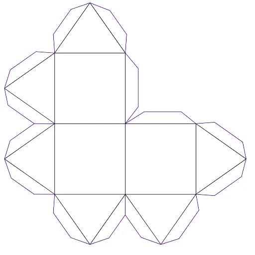
Yoshimoto Cube Net (make 8)
Loading the math board and drawing, please wait…
This example demonstrates how to construct 8 Yoshimoto Cube nets through unfolding diagrams. Core math concepts include solid geometry, polygon construction, and geometric drawing. Construction highlights involve using GeoGebra commands like Segment, Point, Line, Circle, Intersect, and OrthogonalLine for point-line-circle intersections and perpendicular line constructions. Suitable for high school solid geometry teaching or geometric construction practice.
GeoGebra Commands & Parameters
Segment(B, C) → aSegment(C, D) → bSegment(D, E) → cPoint(a) → FSegment(E, F) → dSegment(B, G) → ePoint(b) → HSegment(G, H) → fLine(I, xAxis) → gPoint(g) → JCircle(F, Segment[I, C]) → hPoint(yAxis) → KSegment(K, L) → iPoint(yAxis) → MSegment(M, N) → jIntersect(h, j, 1) → OIntersect(h, i, 1) → PCircle(B, Radius[h]) → kCircle(E, Radius[k]) → pIntersect(p, i, 2) → QOrthogonalLine(I, g) → lIntersect(k, l, 2) → RSegment(O, B) → mSegment(O, F) → nSegment(F, P) → qSegment(P, C) → rSegment(C, I) → sSegment(I, H) → tSegment(H, J) → a_1Segment(J, D) → b_1Segment(D, Q) → c_1Segment(Q, E) → d_1Segment(B, R) → e_1Segment(R, G) → f_1Intersect(d, f) → SLine(L, c_1) → g_1Line(L, d_1) → h_1Line(N, f) → i_1Line(M, m) → j_1Line(M, n) → k_1Line(T, e_1) → l_1Line(T, f_1) → m_1Line(U, q) → n_1Line(U, r) → p_1Point(xAxis) → WPoint(xAxis) → ZLine(V, d) → q_1Line(Z, b_1) → r_1Line(Z, a_1) → s_1Line(W, t) → t_1Line(W, s) → a_2Point(l_1) → A_1Segment(B, A_1) → b_2Point(l_1) → B_1Segment(R, B_1) → c_2Segment(A_1, B_1) → d_2Point(m_1) → C_1Segment(R, C_1) → e_2Point(m_1) → D_1Segment(G, D_1) → f_2Segment(C_1, D_1) → g_2Intersect(h_1, i_1) → E_1Segment(G, E_1) → h_2Point(i_1) → F_1Segment(S, F_1) → i_2Point(q_1) → G_1Segment(S, G_1) → j_2Segment(F_1, E_1) → k_2Intersect(m_1, q_1) → H_1Segment(E, H_1) → l_2Segment(G_1, H_1) → m_2Point(h_1) → I_1Segment(E, I_1) → n_2Point(h_1) → J_1Segment(Q, J_1) → p_2Segment(I_1, J_1) → q_2Point(g_1) → K_1Segment(D, K_1) → r_2Point(g_1) → L_1Segment(Q, L_1) → s_2Segment(K_1, L_1) → t_2Point(r_1) → M_1Segment(D, M_1) → a_3Point(r_1) → N_1Segment(J, N_1) → b_3Segment(N_1, M_1) → c_3Intersect(s_1, t_1) → O_1Segment(H, O_1) → d_3Intersect(p_1, t_1) → P_1Point(s_1) → Q_1Segment(J, Q_1) → f_3Segment(Q_1, O_1) → g_3Segment(O_1, P_1) → h_3Point(a_2) → R_1Segment(I, R_1) → i_3Point(a_2) → S_1Segment(R_1, S_1) → j_3Segment(S_1, C) → k_3Point(p_1) → T_1Segment(C, T_1) → l_3Point(p_1) → U_1Segment(T_1, U_1) → m_3Segment(U_1, P) → n_3Point(n_1) → V_1Segment(P, V_1) → p_3Intersect(k_1, n_1) → W_1Segment(V_1, W_1) → q_3Segment(W_1, F) → r_3Point(k_1) → Z_1Segment(W_1, Z_1) → s_3Segment(Z_1, O) → t_3Point(j_1) → A_2Segment(O, A_2) → a_4Point(j_1) → B_2Segment(A_2, B_2) → b_4Segment(B_2, B) → c_4Intersect(s, t) → C_2Point(h_3) → D_2Segment(C_2, D_2) → e_3Intersect(d_3, g_3) → E_2Segment(D_2, E_2) → d_4
AI Drawing Prompt Reference
Draw a net of a cube consisting of six connected squares. Start by drawing two parallel line segments, then place four squares on each segment. Connect the squares with edges to form a mesh-like structure. Adjust the angles and positions to resemble an unfolded cube.
The prompt above was compiled from the original drawing commands and is for reference only.