
Two Cylinders in a Trough - Parametric Diagram
Loading the math board and drawing, please wait…
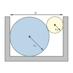
This example demonstrates two cylinders in a trough and their associated free body diagram. Key mathematical concepts include parametric equations and vectors. Using commands such as Translate, Circle, Max, Polygon, Intersect, Point, Vector, Angle, Segment, Rotate, the positions and forces on the cylinders can be constructed. Suitable for high school physics and mathematics education.
GeoGebra Commands & Parameters
Translate(C2, offset) → C2'Circle(C1, r1) → c_1Circle(C2, r2) → c_2Max(y(C1) + r1, y(C2) + r2) → heightPolygon(pts) → troughCircle(C1, r1) → c_1'Polygon(pts) → trough_{edge}Intersect(c_1, c_2, 1) → APoint(c_1') → BPoint(c_1') → CCircle(C2, r2) → c_2'Translate(c_2, offset) → c_3Translate(A, offset) → A'Vector(C1, C1 - (vecLength * j)) → w1Vector(C - (vecLength * i), C) → f_cVector(B - (vecLength * j), B) → f_bVector(D + (vecLength * i), D) → f_dVector(C2', C2' - (vecLength * j)) → w2Angle(C1 + ((2 * r1) * i), C1, C2) → θ'_1Segment(C1, A) → witness_1Segment(C2', C2' - ((1.5 * r2) * i)) → witness_2'Segment(Translate[C2, offset], Translate[A, offset]) → witness_1'Angle(witness_2', witness_1') → θ_1Segment(C1, C1 + ((1.5 * r1) * i)) → witness_2Vector(A - (vecLength * UnitVector[Vector[C2, C1]]), A) → f_aVector(A' - (vecLength * UnitVector[Vector[C1, C2]]), A') → f_a'Translate(c_2, offset) → c_3'Vector((0, 0) + (width * i) + ((0.2 + height) * j), (0, 0) + ((0.2 + height) * j)) → d'Vector((0, 0) + ((0.2 + height) * j), (0, 0) + (width * i) + ((0.2 + height) * j)) → dRotate(Vector[C1, C], 135°) → r_1Rotate(Vector[C2, C2 + (r2 * i)], -45°) → r_2Polygon(C1, C2, (x(C2), y(C1))) → t1, t1_2, t1_1, t1_3Angle((x(C2), y(C1)), C1, C2) → θ_2
AI Drawing Prompt Reference
Draw two cylinders inside a trough with their associated free-body diagrams. The cylinders are generated by rotating circles, and the trough is a polygon. First, sketch the outlines of the cylinders and find their intersection points with the trough. Then, add vectors for gravity, normal force, and friction on the cylinders, along with helper lines and angle markings. Combine all elements to form the complete illustration, showcasing the use of parametric equations and vectors.
The prompt above was compiled from the original drawing commands and is for reference only.