
Concentrated Forces: Shear and Bending Moment Diagrams
Loading the math board and drawing, please wait…
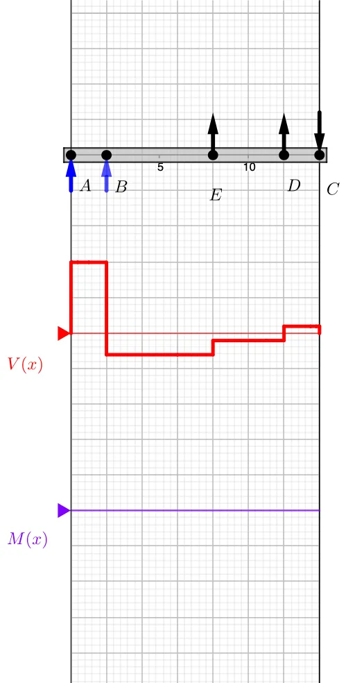
This example demonstrates the construction of Shear and Bending Moment diagrams under concentrated forces on a beam. Key math concepts include Integral Calculus, Sine functions, and Calculus. The construction utilizes GeoGebra commands like Point, Vector, If, Sort, Max, Min, member, Segment, Textfield, and Polygon. Suitable for high school students and engineering professionals studying structural mechanics and engineering applications.
GeoGebra Commands & Parameters
Point(xAxis) → BPoint(xAxis) → EPoint(xAxis) → DPoint(xAxis) → CPoint(xAxis) → AVector(A, E) → r_EVector(A, D) → r_DVector(A, B) → r_BVector(A, C) → r_CIf(x(D) < x(E), D, E) → startIf(start ≟ D, E, D) → endSort(Unique[x({A, B, C, D, E})]) → pointsPoint(x = ((-AxisStepX[])) / 4) → VMax(x({A, C, B, D, E})) → rightMin(x({A, C, B, D, E})) → leftmember((Min[x({A, C, E, D, B})], 0), (Max[x({A, C, E, D, B})], 0), (0.2 * AxisStepY[])) → beam, beam1, beam2, beam3, beam4Segment((x(A), v'(x(A))), (x(A), v'(x(A) + 0.001))) → v_ASegment((x(B), v'(x(B))), (x(B), v'(x(B) + 0.001))) → v_BPoint(x = ((-AxisStepX[])) / 4) → MSegment((x(C), v'(x(C))), (x(C), v'(x(C) + 0.001))) → v_CSegment(V', (x(V'), v'(right))) → v_rMax(Join[{{0}, y(Sequence[Max[m, points(k), points(k + 1)], k, 1, Length[points] - 1])}]) → M_{max}Min(Join[{{0}, y(Sequence[Min[v, points(k), points(k + 1)], k, 1, Length[points] - 1])}]) → V_{min}Textfield(Scale_V) → InputBox1Textfield(Scale_M) → InputBox2Polygon((right, y(Corner[2])), (right, y(Corner[3])), Corner[3], Corner[2]) → mask, mask_l, mask_t, mask_r, mask_bSegment((0, y(V)), (right, y(V))) → VaxisSegment((0, y(M)), (right, y(M))) → MaxisMax(Join[{{0}, y(Sequence[Max[v, points(k), points(k + 1)], k, 1, Length[points] - 1])}]) → V_{max}Min(Join[{{0}, y(Sequence[Min[m, points(k), points(k + 1)], k, 1, Length[points] - 1])}]) → M_{min}Segment((x(D), v'(x(D))), (x(D), v'(x(D) + 0.001))) → v_DSegment((x(E), v'(x(E))), (x(E), v'(x(E) + 0.001))) → v_EIf(F_C > 0, Vector[C + (1.2 * j), C], Vector[C, C + (1.2 * j)]) → p_CIf(F_E > 0, Vector[E + (1.2 * j), E], Vector[E, E + (1.2 * j)]) → p_EIf(F_D > 0, Vector[D + (1.2 * j), D], Vector[D, D + (1.2 * j)]) → p_DVector(A - j, A) → aVector(B - j, B) → b
AI Drawing Prompt Reference
Draw shear and bending moment diagrams for a beam under concentrated forces, including five key points on the horizontal axis, vectors showing relationships between points, and marking maxima and minima of shear and moment. Start with the beam and key points, then draw the shear and moment diagrams based on force directions, and finally label values and units.
The prompt above was compiled from the original drawing commands and is for reference only.