
Geometric & Vector Proof of Centripetal Force
Loading the math board and drawing, please wait…
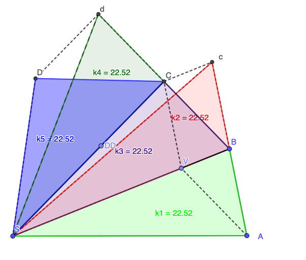
This example constructs a circular-motion geometry to visualize how centripetal force relates to the change in direction of motion. It emphasizes key ideas such as vector direction/radial–tangential decomposition, circle geometry, and equation-form relationships that mirror Newton’s reasoning. The construction uses GeoGebra primitives to build the scene: creating segments and lines from essential points, drawing a guiding circle, finding intersections to locate key points, and assembling polygons to represent combined geometric quantities. The listed objects (e.g., points like S, A, B, C; parameters/expressions such as f, g, h; and direction/velocity-related vectors like V with multiple indexed geometric quantities) reflect a workflow where geometric elements are assembled into the relationships needed for the proof. Suitable for advanced high school through early undergraduate use, especially for instruction on centripetal acceleration, vectors, and calculus-assisted geometric reasoning.
GeoGebra Commands & Parameters
Segment(S, A) → fSegment(A, B) → gSegment(B, S) → hPoint(h) → VLine(A, B) → iCircle(B, A) → c_{1}Intersect(c_{1}, i, 2) → cSegment(B, c) → jLine(V, g) → kLine(c, h) → lIntersect(k, l) → CSegment(C, c) → mSegment(V, C) → nSegment(C, S) → pSegment(c, S) → qSegment(B, C) → rPolygon(S, A, B) → k1, b, s, aPolygon(S, B, c) → k2, c_2, s_1, b_1Polygon(S, B, C) → k3, c_3, s_2, b_2Segment(B, V) → tSegment(A, V) → d_{2}Line(B, C) → eCircle(C, B) → d_1Intersect(d_1, e, 2) → dSegment(d, S) → f_1Point(p) → DDLine(DD, e) → g_1Line(d, p) → h_1Intersect(g_1, h_1) → DSegment(C, d) → i_1Segment(d, D) → j_1Segment(D, S) → k_1Polygon(S, C, d) → k4, d_3, s_3, c_4Polygon(S, C, D) → k5, d_4, s_4, c_5
AI Drawing Prompt Reference
Draw a plane geometry scene starting with three points S, A, and B, forming the triangle by segment connections between them. Construct a circle using B and A as defining elements, then intersect this circle with the line through A and B to obtain a new point c; draw the segment from B to c. Create a direction vector V by placing a point associated with the earlier intersection result, and use V with one of the triangle’s side directions to define two lines whose intersection gives a key point C. Then draw segments that connect C to c and connect C to S, as well as a segment from C to the endpoint associated with V. Finally, assemble several polygons to cover the regions corresponding to combinations S-A-B, S-B-c, S-B-C, and S-C-(the constructed point linked to the circle intersection), emphasizing the geometric relationship behind radial and tangential direction changes.
The prompt above was compiled from the original drawing commands and is for reference only.