
Shear and Bending Moment Diagrams: Concentrated Moments on a Beam
Loading the math board and drawing, please wait…
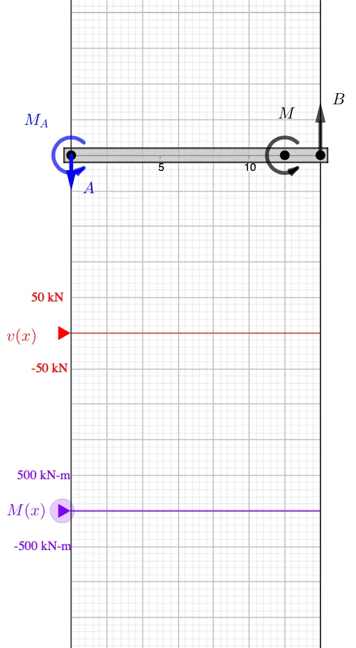
① This example demonstrates how to construct shear force and bending moment diagrams for a beam subjected to concentrated moments, clearly showing the effect of applied moments on internal forces. ② Core mathematical concepts include static equilibrium, the differential relationships between load, shear, and moment, piecewise functions, and handling discontinuities at the point of moment application, involving integration and differentiation. ③ Construction highlights: using GeoGebra commands such as Point, Vector, Segment, and Polygon to build the beam geometry, If, Max, Min, and member to manage piecewise conditions, Textfield for parameter input, and the Moment object to compute the bending moment contribution from concentrated moments, finally generating the shear (V) and moment (M) diagrams. ④ Suitable for university courses in engineering mechanics, structural analysis, or calculus when teaching shear-moment diagrams, and also useful for high school physics extensions or classroom demonstrations.
GeoGebra Commands & Parameters
Point(xAxis) → AIf(x(A) ≟ 0, -0.5, 0.5) → wall_hPoint(xAxis) → DPoint(xAxis) → CPoint(xAxis) → BPoint(xAxis) → EVector(A, C) → r_{P_C}Vector(A, B) → r_BIf(x(D) < x(E), D, E) → startIf(start ≟ D, E, D) → endPoint(x = ((-AxisStepX[])) / 4) → VMax(x({A, C, B, D, E})) → rightMin(x({A, C, B, D, E})) → leftmember((Min[x({A, C, E, D, B})], 0), (Max[x({A, C, E, D, B})], 0), (0.2 * AxisStepY[])) → beam, beam1, beam2, beam3, beam4Segment((x(A), v'(x(A))), (x(A), v'(x(A) + 0.001))) → v_ASegment((x(B), v'(x(B))), (x(B), v'(x(B) + 0.001))) → v_BPoint(x = ((-AxisStepX[])) / 4) → MSegment((x(C), v'(x(C))), (x(C), v'(x(C) + 0.001))) → v_CSegment(V', (x(V'), v'(right))) → v_rTextfield(Scale_V) → InputBox1Textfield(Scale_M) → InputBox2Polygon((right, y(Corner[2])), (right, y(Corner[3])), Corner[3], Corner[2]) → mask, mask_l, mask_t, mask_r, mask_bSegment((0, y(V)), (right, y(V))) → VaxisSegment((0, y(M)), (right, y(M))) → MaxisSegment((x(D), m'(x(D))), (x(D), m'(x(D) + 0.001))) → m_DMoment(D, M_D) → MD_1, MD_2, MD_3Moment(A, 1) → MA_1, MA_2, MA_3Segment((x(A), m'(x(A) - 0.0001)), (x(A), m'(x(A) + 0.001))) → m_ASegment((x(A), m'(x(A))), M') → m_rSegment((0, m'(0.0001)), (0, y(M))) → m_LMax(Join[{{0}, y(Sequence[Max[v, points(k), points(k + 1)], k, 1, Length[points] - 1])}]) → V_{max}Min(RemoveUndefined[Join[{{0}, y(Sequence[Min[v, points(k), points(k + 1)], k, 1, Length[points] - 1])}]]) → V_{min}Max(Join[{{0}, y(Sequence[Max[m, points(k), points(k + 1)], k, 1, Length[points] - 1])}]) → M_{max}Min(Join[{{0}, y(Sequence[Min[m, points(k), points(k + 1)], k, 1, Length[points] - 1])}]) → M_{min}If(F_A ≥ 0, Vector[A - j, A], Vector[A, A - j]) → aIf(F_B ≥ 0, Vector[B, B + (1.5 * j)], Vector[B + (1.5 * j), B]) → bPolygon(A + {(0, 2), (wall_h, 2), (wall_h, -2), (0, -2)}) → wallIf(P_C ≥ 0, Vector[C, C + (1.5 * j)], Vector[C + (1.5 * j), C]) → p_C
AI Drawing Prompt Reference
Draw a simply supported beam with concentrated moments applied at points D and E. Start by setting up the coordinate axes, then place points A, C, B, D, and E on the x-axis. Define the beam's geometry using vectors and create its segments with points and vectors. Use Max and Min functions to determine the beam's boundaries, and define its shape with Piecewise functions. Next, draw the shear force and bending moment diagrams, set the scale with input boxes. Finally, add walls and arrows to mark key points, showing the internal forces under the concentrated moments.
The prompt above was compiled from the original drawing commands and is for reference only.