
Screw Bisection of a Cube
Loading the math board and drawing, please wait…
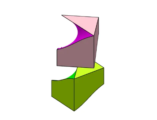
This example demonstrates the geometric phenomenon of bisecting a cube through a screw motion. It involves core mathematical concepts such as spatial geometry, helical motion, and bisection principles. The construction utilizes GeoGebra commands/objects like Point, Cube, Surface, CurveCartesian, Rotate, Translate, Polygon, and Segment. Suitable for high school and above, exploring applications in solid geometry, spatial transformations, and parametric equations.
GeoGebra Commands & Parameters
Point(Circle[A, Distance[B, A], Segment[B, A]]) → CCube(B, A, C) → a, D, faceCDHG, faceEFGH, edgeBD, edgeAB, edgeAC, edgeCD, edgeBE, edgeDH, edgeEH, edgeEF, E, edgeAF, edgeFG, edgeCG, edgeGH, F, G, H, faceABDC, faceBDHE, faceABEF, faceACGFSurface((u * cos(t)), (u * sin(t)), (sqrt(2) * t / π), t, 0, π, u, 0, 1.5) → bCurveCartesian((r(t) * cos(t)), (r(t) * sin(t)), (sqrt(2) * t / π), t, 0, π / 2) → cCurveCartesian((p(t) * cos(t)), (p(t) * sin(t)), (sqrt(2) * t / π), t, π / 2, π) → dRotate(b, π) → b'Rotate(c, π) → c'Rotate(d, π) → d'Surface((u * x(d(t))) + ((1 - u) * x(d'(t))), (u * y(d(t))) + ((1 - u) * y(d'(t))), (u * z(d(t))) + ((1 - u) * z(d'(t))), t, π / 2, π, u, 0, 1) → eSurface((u * x(c(t))) + ((1 - u) * x(c'(t))), (u * y(c(t))) + ((1 - u) * y(c'(t))), (u * z(c(t))) + ((1 - u) * z(c'(t))), t, 0, π / 2, u, 0, 1) → fTranslate(Rotate[e, n], Vector[(0, 0, (sqrt(2) / π * n))]) → gTranslate(Rotate[f, n], Vector[(0, 0, (sqrt(2) / π * n))]) → hTranslate(Rotate[Polygon[H, F, G], n], Vector[(0, 0, (sqrt(2) / π * n))]) → t1Translate(Rotate[Polygon[D, B, A], n], Vector[(0, 0, (sqrt(2) / π * n))]) → t2Translate(Rotate[Surface[x(c(t)), y(c(t)), ((1 - u) * z(c(t))) + (u * sqrt(2)), t, 0, π / 2, u, 0, 1], n], Vector[(0, 0, (sqrt(2) / π * n))]) → jTranslate(Rotate[Surface[x(d(t)), y(d(t)), ((1 - u) * z(d(t))) + (u * sqrt(2)), t, π / 2, π, u, 0, 1], n], Vector[(0, 0, (sqrt(2) / π * n))]) → iTranslate(Rotate[Surface[x(d'(t)), y(d'(t)), (u * z(d'(t))), t, π / 2, π, u, 0, 1], n], Vector[(0, 0, (sqrt(2) / π * n))]) → kTranslate(Rotate[Surface[x(c'(t)), y(c'(t)), ((1 - u) * z(c'(t))), t, 0, π / 2, u, 0, 1], n], Vector[(0, 0, (sqrt(2) / π * n))]) → lSurface(x(c(t)), y(c(t)), ((1 - u) * z(c(t))), t, 0, π / 2, u, 0, 1) → mSurface(x(d(t)), y(d(t)), ((1 - u) * z(d(t))), t, π / 2, π, u, 0, 1) → oSurface(x(c'(t)), y(c'(t)), ((1 - u) * z(c'(t))) + (u * sqrt(2)), t, 0, π / 2, u, 0, 1) → qSurface(x(d'(t)), y(d'(t)), ((1 - u) * z(d'(t))) + (u * sqrt(2)), t, π / 2, π, u, 0, 1) → sPolygon(F, H, E) → t3, e_1, f_1, h_1Polygon(A, C, D) → t4, d_1, a_1, c_1Translate(Rotate[Surface[x(c'(t)), y(c'(t)), ((1 - u) * z(c'(t))), t, 0, π / 2, u, 0, 1], n], Vector[(0, 0, (sqrt(2) / π * n))]) → tTranslate(Rotate[c, n], Vector[(0, 0, (sqrt(2) / π * n))]) → uTranslate(Rotate[c', n], Vector[(0, 0, (sqrt(2) / π * n))]) → vTranslate(Rotate[d', n], Vector[(0, 0, (sqrt(2) / π * n))]) → wTranslate(Rotate[d, n], Vector[(0, 0, (sqrt(2) / π * n))]) → b_1Translate(Segment[Rotate[A, n], Rotate[F, n]], Vector[(0, 0, (sqrt(2) / π * n))]) → g_1Translate(Segment[Rotate[G, n], Rotate[F, n]], Vector[(0, 0, (sqrt(2) / π * n))]) → i_1Translate(Segment[Rotate[G, n], Rotate[H, n]], Vector[(0, 0, (sqrt(2) / π * n))]) → j_1Translate(Segment[Rotate[F, n], Rotate[H, n]], Vector[(0, 0, (sqrt(2) / π * n))]) → k_1Translate(Rotate[Segment[G, Midpoint[G, C]], n], Vector[(0, 0, (sqrt(2) / π * n))]) → l_1Translate(Segment[Rotate[A, n], Rotate[B, n]], Vector[(0, 0, (sqrt(2) / π * n))]) → m_1Translate(Rotate[Segment[B, Midpoint[B, E]], n], Vector[(0, 0, (sqrt(2) / π * n))]) → n_1Translate(Segment[Rotate[D, n], Rotate[B, n]], Vector[(0, 0, (sqrt(2) / π * n))]) → p_1Translate(Segment[Rotate[D, n], Rotate[A, n]], Vector[(0, 0, (sqrt(2) / π * n))]) → q_1Segment(H, F) → r_1Segment(H, E) → s_1Segment(E, F) → t_1Segment(A, D) → f_2Segment(A, C) → g_2Segment(D, C) → h_2Segment(H, D) → i_2Segment(E, Midpoint[B, E]) → j_2Segment(C, Midpoint[C, G]) → k_2
AI Drawing Prompt Reference
Draw a cube and demonstrate how to bisect it through a screw motion. Start by creating a cube, then construct a helical surface. Use rotations and translations to combine the helical surface with the cube, forming a bisection effect. The final image should include the cube, helical surface, and related rotated and translated geometric objects, clearly showing the bisection process.
The prompt above was compiled from the original drawing commands and is for reference only.