
Parallel Projection of a 4-Cube
Loading the math board and drawing, please wait…
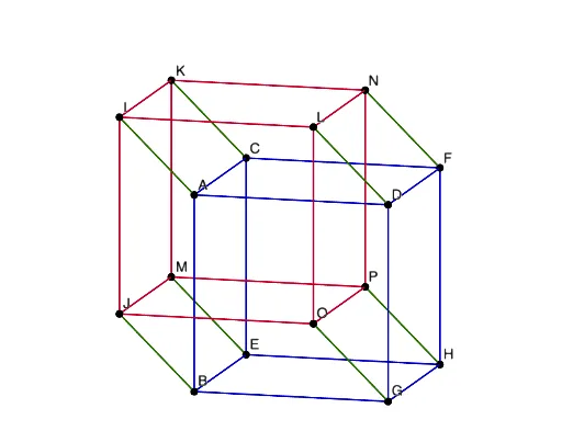
This example demonstrates the parallel projection of a 4-Cube (Tesseract) into 3D space. It involves core mathematical concepts such as hypercube geometry, projection transformations, and solid geometry. The construction uses GeoGebra commands like Segment and various objects (a, b, c, A, B, C, D, E, F, G, H, f, g, h, i, j, k, l, m, n, p, q, r, d, I, J, K, L, M, N, O, P, s, t, e, f_1, g_1, h_1, i_1, j_1) to visualize the shape and its projection. Suitable for high school students and above, or as a teaching tool for understanding higher-dimensional geometry.
GeoGebra Commands & Parameters
Segment(A, D) → fSegment(A, C) → gSegment(C, F) → hSegment(F, D) → iSegment(G, B) → jSegment(B, E) → kSegment(E, H) → lSegment(H, G) → mSegment(A, B) → nSegment(C, E) → pSegment(F, H) → qSegment(D, G) → rSegment(I, L) → sSegment(K, I) → tSegment(K, N) → eSegment(N, L) → f_1Segment(J, I) → g_1Segment(M, K) → h_1Segment(J, O) → i_1Segment(O, L) → j_1Segment(M, J) → k_1Segment(M, P) → l_1Segment(P, N) → m_1Segment(P, O) → n_1Segment(N, F) → p_1Segment(K, C) → q_1Segment(A, I) → r_1Segment(D, L) → s_1Segment(G, O) → t_1Segment(B, J) → a_1Segment(M, E) → b_1Segment(P, H) → c_1
AI Drawing Prompt Reference
Draw a parallel-projection wireframe of a 4-dimensional hypercube (tesseract) into 3D space. In one 3D coordinate view, place two corresponding sets of vertices. Connect segments to build the main outline of the first solid, then add the remaining segments that form its internal and face edges. Next, connect the vertices of the second set to their projected counterparts from the first set to create the side connections between the two 3D parts. Follow the construction step-by-step: first create several backbone edges to establish the overall shape, then complete all remaining edges so that each face has its boundary segments and the full projection resembles a tesseract line structure.
The prompt above was compiled from the original drawing commands and is for reference only.