
Cross-sections of a 3-Cube in Its Projection
Loading the math board and drawing, please wait…
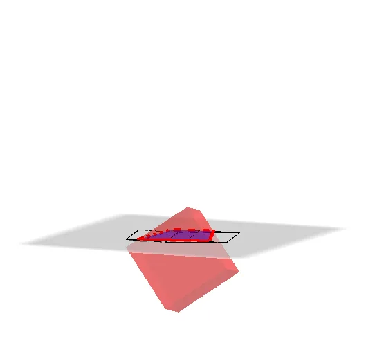
This example demonstrates how to analyze cross-sections of a 3-dimensional cube within its 2D projection. The core mathematical concepts include solid geometry (polyhedron sections), coordinate geometry, and the properties of plane-solid intersections. Construction highlights: Using the Plane command to create cutting planes, Cube command to build the 3D cube model, IntersectPath command to find intersection curves, combined with Line and Segment commands to draw cross-section outlines. By controlling plane position parameters, users can observe different types of cross-sections (triangles, quadrilaterals, pentagons, hexagons). Suitable for high school and early college students studying solid geometry, as well as math competition training to enhance spatial visualization skills.
GeoGebra Commands & Parameters
Plane((0, 0, 0), (1, 0, 0), (0, 1, 0)) → pCube(A, B, C) → acube, D, faceCDHG, faceEFGH, edgeAD, edgeAB, edgeBC, edgeCD, edgeAE, edgeDH, edgeEH, edgeEF, E, edgeBF, edgeFG, edgeCG, edgeGH, F, G, H, faceABCD, faceADHE, faceABFE, faceBCGFIntersectPath(p, acube) → cubsec_{1}, M, n, r, i, N, O, Q, U, W, k, l, mLine((0, 0), (1, 0)) → fLine((0, 0), (0, 1)) → gSegment((x(A), y(A)), (x(B), y(B))) → jSegment((x(C), y(C)), (x(B), y(B))) → qSegment((x(C), y(C)), (x(D), y(D))) → sSegment((x(A), y(A)), (x(D), y(D))) → tSegment((x(A), y(A)), (x(E), y(E))) → dSegment((x(E), y(E)), (x(F), y(F))) → eSegment((x(G), y(G)), (x(H), y(H))) → f_1Segment((x(H), y(H)), (x(D), y(D))) → g_1Segment((x(H), y(H)), (x(E), y(E))) → h_1Segment((x(F), y(F)), (x(B), y(B))) → i_1Segment((x(G), y(G)), (x(C), y(C))) → j_1Segment((x(F), y(F)), (x(G), y(G))) → k_1
AI Drawing Prompt Reference
Draw a cross-section of a 3D cube in its 2D projection. Key objects include a cutting plane, a cube model, and intersection curves formed by the plane intersecting the cube. Line segments are used to draw the outline of the cross-section. By controlling the position of the cutting plane, different shapes such as triangles, quadrilaterals, pentagons, and hexagons can be observed. The construction order is to first create the plane and cube, then compute the intersection curves, and finally draw the line segment outlines.
The prompt above was compiled from the original drawing commands and is for reference only.