
Modular Sectioning of a Cube via Symmetry
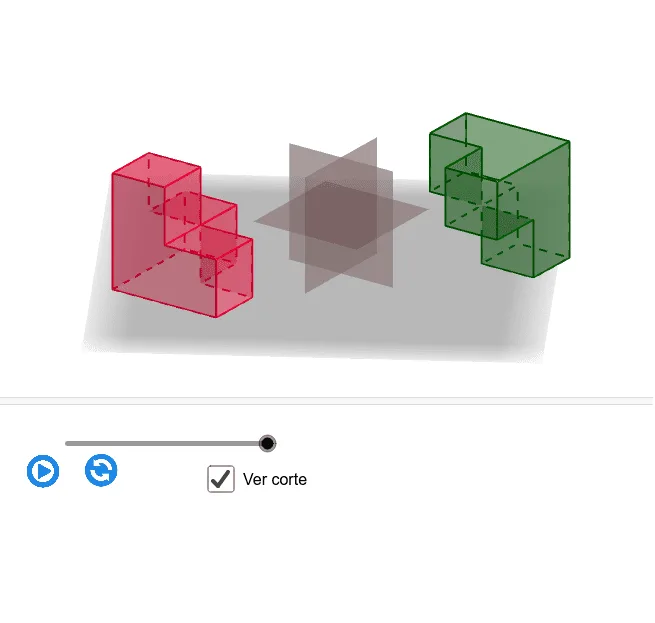
Loading the math board and drawing, please wait…
This example demonstrates a “modular/stepwise” sectioning of a cube, producing multiple symmetric cross-sections and showing how faces and edges correspond under a fixed construction rule. The key mathematics includes solid geometry (cube subdivision), geometric relationships among faces and edges, midpoint construction, and the use of rigid transformations—rotation, translation, and reflection—to reveal symmetry in the resulting partitions. Construction highlights from the GeoGebra command summary: Circle and Point are used to generate auxiliary geometric objects (e.g., b, O, r, c, t, sl); Rotate, Translate, and Mirror create repeated and symmetric parts; Cube builds the 3D solid (faces such as caraABCD, caraADHE, caraABFE, caraBCGF, caraCDHG, caraEFGH); Midpoint and Sequence generate subdivision points (e.g., A1–A8, B4, B2); Line, Segment, Vector, and Polygon then connect these points to form edge and section outlines (edges like aristaAB, aristaBC_1, aristaCD, aristaEF, aristaFG_1, aristaGH_1 and the polygonal face objects). Suitable for advanced secondary school and early university learners for lessons on symmetry transformations and cube sectioning, as well as classroom exploration and geometric modeling.
GeoGebra Commands & Parameters
Circle(O, r, xOyPlane) → cPoint(c) → A1Rotate(A1, π / 2, O) → A2Cube(A1, A2, zAxis) → a, A3, caraBCGF, caraCDHG, caraEFGH, aristaAD_1, aristaAB, aristaBC_1, aristaCD, aristaAE_1, aristaDH, arista, A4, aristaEF, aristaBF, aristaFG_1, aristaCG_1, aristaGH_1, A5, A6, A7, A8, caraABCD, caraADHE, caraABFEMidpoint(A1, A7) → centroSequence(Max[0, Min[1, t - s]], s, 0, 1) → slMidpoint(A4, A8) → B4Midpoint(A6, A2) → B2Line(A5, A3) → kSegment(A7, A1) → hMidpoint(A1, A5) → B1Midpoint(A3, A7) → B3Midpoint(A1, A2) → B5Midpoint(A2, A3) → B6Midpoint(A3, A4) → B7Midpoint(A4, A1) → B8Midpoint(A5, A6) → BAMidpoint(A6, A7) → BBMidpoint(A7, A8) → BCMidpoint(A8, A5) → BDMidpoint(A1, A6) → O1Midpoint(A2, A7) → O2Midpoint(A3, A8) → O3Midpoint(A8, A1) → O4Midpoint(A5, A7) → O5Vector(A4, A1) → u1Vector(A4, A3) → u2Vector(A4, A8) → u3Polygon(B1, B2, B3, B4) → c1, b1, b2_1, b3, b4Polygon(B5, B7, BC, BA) → c3, b5, b7, bc, baTranslate(c1, u1) → c1'Polygon(B8, B6, BB, BD) → c2, f, g, i, jTranslate(c2, u2) → c2'Translate(c3, u3) → c3'Translate(c1', Vector[((-sl(1)) * u1)]) → c1''Translate(c2', Vector[((-sl(1)) * u2)]) → c2''Translate(c3', Vector[((-sl(1)) * u3)]) → c3''Polygon(A1, B5, O1, B1) → d0, a1, l, o1, mPolygon(B1, O4, centro, O1) → d1, n, o4, p, qPolygon(B5, O, centro, O1) → d2, s, o, e, f_1Polygon(O4, centro, O5, BD) → d3, g_1, h_1, o5, bdPolygon(centro, O3, BC, O5) → d4, i_1, o3, j_1, k_1Polygon(BD, O5, BC, A8) → d5, l_1, m_1, n_1, a8Polygon(O, B6, O2, centro) → d6, o_1, b6, o2, p_1Polygon(B6, A3, B3, O2) → d7, q_1, a3, r_1, s_1Polygon(centro, O2, B3, O3) → d8, t_1, a_1, b_1, c_1Polygon(A4, A1, B1, O4, BD, A8) → d9, a4, d_1, e_1, f_2, g_2, h_2Polygon(A3, A4, A8, BC, O3, B3) → da, i_2, j_2, k_2, l_2, m_2, n_2Translate(ll1, Vector[((-sl(2)) * v / 2)]) → ll2Mirror(ll2, centro) → ll3
AI Drawing Prompt Reference
Draw a cube and generate multiple symmetric cross-sections through rotation, translation, and reflection. Start by drawing the cube, then find its vertices and center point. Generate a series of midpoints and use these midpoints to construct multiple cross-sections, each of which is created by rotating and reflecting symmetric parts.
The prompt above was compiled from the original drawing commands and is for reference only.