
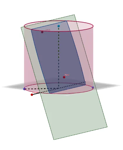
Interactive Demonstration of Cutting a Cylinder with a Plane
Loading the math board and drawing, please wait…
In collections
Cutting solids by a plane
This example demonstrates how to use an interactive plane to cut a cylinder. Key mathematical concepts include the intersection of a plane and a cylinder in solid geometry. Using GeoGebra commands such as Point, Cube, Line, Circle, and Plane, a dynamic graphical representation of the cutting process is constructed. Suitable for middle school and above students or teachers for teaching and learning.
GeoGebra Commands & Parameters
Point(Circle[B, Distance[A, B], Segment[A, B]]) → CCube(A, B, C) → a, D, faceCDHG, faceEFGH, arêteAD, arêteAB, arêteBC, arêteCD, arêteAE, arêteDH, arêteEH, arêteEF, E, arêteBF, arêteFG, arêteCG, arêteGH, F, G, H, faceABCD, faceADHE, faceABFE, faceBCGFMidpoint(C, A) → IMidpoint(F, H) → JLine(J, I) → fCircle(I, Distance[A, B], f) → cPoint(c) → KMidpoint(F, C) → MMirror(K, I) → K'Line(K', K) → gCircle(I, (1.2 * Distance[A, B]), g) → dPoint(d) → LPlane(L, K, K') → pCircle(K', L, K) → eCenter(e) → NOrthogonalLine(N, p) → hPoint(h) → OVector(I, O) → uTranslate(p, u) → p'Segment(K', K) → bLine(L, b) → f_1Point(arêteEF) → D_1OrthogonalLine(K, p) → h_1Plane(K', h_1) → p_1OrthogonalLine(K, p_1) → k_1Line(K', k_1) → l_1Intersect(f_1, l_1) → E_1Intersect(k_1, f_1) → F_1Mirror(F_1, K) → G_1Mirror(E_1, K') → H_1Polygon(F_1, E_1, H_1, G_1) → q2, m_1, e_1, n_1, q_1Translate(q2, u) → q2'Circle(I, Distance[I, A], f) → qPoint(f) → SSegment(A, I) → iSegment(I, S) → jCylinder(q, (-Distance[I, S])) → l, t, mIntersectPath(p', l) → k
AI Drawing Prompt Reference
Draw a cylinder and use an interactive plane to cut it, showing the changing shape of the cross-section. Start by constructing the cylinder, then create a circle that includes the midpoint of the cylinder. Generate another auxiliary circle through mirroring and rotation. Define a plane and find its intersection with the cylinder to determine the cutting position. Finally, translate the plane along a specific direction to observe the cutting effect.
The prompt above was compiled from the original drawing commands and is for reference only.