
Different Cube Net Arrangements
Loading the math board and drawing, please wait…
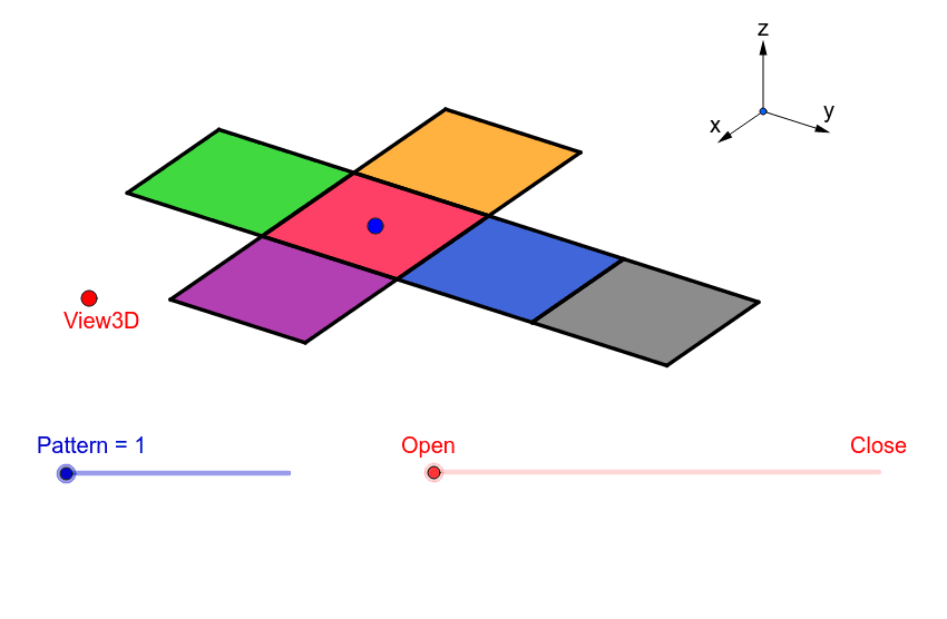
This example demonstrates different net arrangements of a cube. Key mathematical concepts include solid geometry and geometric construction. Using commands like Vector, Translate, OrthogonalLine, and Polygon in GeoGebra, various net arrangements of a cube can be constructed. Suitable for middle school and above students or teachers to understand the spatial structure of a cube.
GeoGebra Commands & Parameters
Vector(B_1, Z) → wVector(B_1, Y) → vVector(B_1, X) → uTranslate(A, Vector[(2 * v)]) → A'Translate(P, Vector[(2 * v)]) → P'OrthogonalLine(View3D, yAxis) → a_1OrthogonalLine(View3D, xAxis) → b_1Polygon(L, K, N, M) → poly1, l, k_1, n, mPolygon(K, P, Q, N) → poly2, k_2, p, q, n_1Polygon(L, M, S, R) → poly3, l_1, m_1, s, rPolygon(N, V, W, M) → poly4, n_2, v_1, w_1, m_2Polygon(K, T, U, L) → poly5, k_3, t, u_1, l_2Polygon(B, Q, P, A) → poly6, b_2, q_1, p_1, a_2Midpoint(R, M) → DTranslate(S, Vector[(-((2 * v)))]) → S'Segment(S, C) → eTranslate(M, Vector[(-2 * v)]) → M'Segment(M, E) → fSegment(E, C) → hTranslate(N, Vector[(-2 * v)]) → N'Translate(Q, Vector[(-2 * v)]) → Q'_1Segment(Q, F) → iSegment(N, G) → jSegment(G, F) → d_1Translate(Q, Vector[(-2 * v)]) → Q'_2Translate(B, Vector[(-2 * v)]) → B'_1Segment(B, I) → e_1Segment(I, H) → f_1Segment(H, Q) → g_1Translate(K, Vector[(2 * v)]) → K'Translate(P, Vector[(2 * v)]) → P'_1Segment(P, J) → h_1Segment(J, A_1) → i_1Segment(A_1, K) → j_1Segment(B, H_1) → s_1Segment(H_1, C_1) → cSegment(C_1, A) → r_1Midpoint(N, P) → D_1Midpoint(k_1) → F_1Segment(A, G_1) → t_1Segment(G_1, I_1) → c_2Segment(I_1, P) → d_2Segment(J, K_1) → f_2Segment(P, L_1) → e_2Segment(L_1, K_1) → g_2Segment(M, W) → h_2Mirror(L_1, F_1) → O_1Mirror(K_1, F_1) → P_1Segment(M, M_1) → i_2Segment(N_1, J_1) → j_2Segment(J_1, M_1) → p_2Polygon(M, E, C, S) → poly7, q_2, r_2, s_2, t_2Polygon(Q, N, G, F) → poly8, q_3, n_3, g_3, f_3Polygon(B, Q, H, I) → poly9, b_3, q_4, h_3, i_3Polygon(J, A_1, K, P) → poly10, j_3, a_3, k_4, p_3Polygon(C_1, A, B, H_1) → poly11, c_3, a_4, b_4, h_4Polygon(G_1, I_1, P, A) → poly12, g_4, i_4, p_4, a_5Polygon(K_1, J, P, L_1) → poly13, k_5, j_4, p_5, l_3Polygon(M, M_1, J_1, N_1) → poly14, m_3, m_4, j_5, n_4
AI Drawing Prompt Reference
Draw different net arrangements of a cube. Start by defining three vectors u, v, and w along the x, y, and z axes, respectively. Then, translate points A and P, and rotate points S, M, N, and Q to form the faces of the net. Finally, connect the points to create polygons, showing six different net arrangements of the cube.
The prompt above was compiled from the original drawing commands and is for reference only.