
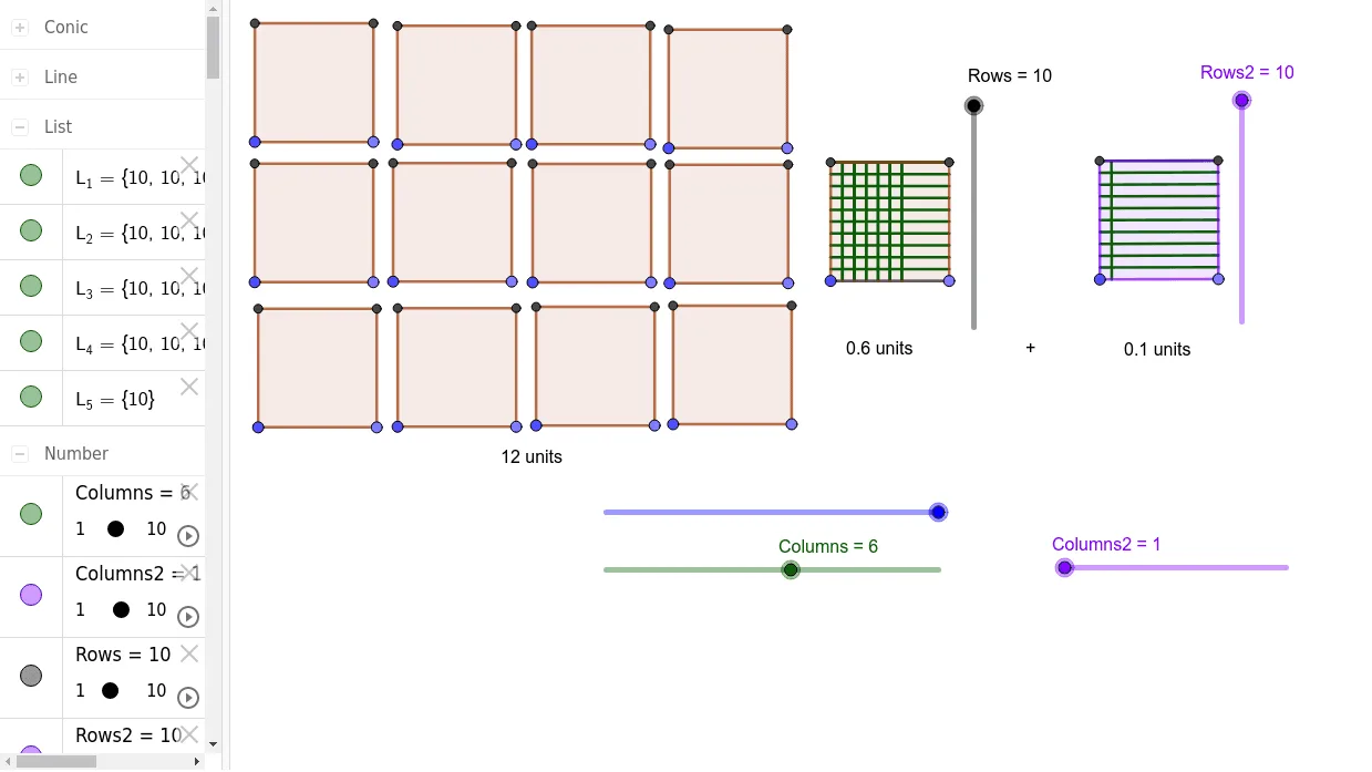
Decimal Addition Example: Show 12.6 units + 0.1 units
Loading the math board and drawing, please wait…
This example demonstrates how to use GeoGebra to visualize the addition of two decimal units (12.6 and 0.1). It involves core math concepts like decimal addition, unit measurement, and numerical calculation. The construction uses commands/objects such as Point, Segment, OrthogonalLine, Circle, Intersect, Line, Polygon, and Sequence. Suitable for elementary and middle school students learning decimal operations and geometric intuition.
GeoGebra Commands & Parameters
Point(Circle[B, blocks]) → CSegment(B, C) → fOrthogonalLine(B, f) → gOrthogonalLine(C, f) → hCircle(B, Rows) → cIntersect(c, g, 2) → ALine(A, g) → iLine(A, f) → jIntersect(h, j) → DPolygon(B, C, D, A) → q1, b, c_1, d, aSequence(Segment[B + (i * (1, 0)), A + (i * (1, 0))], i, 1, Columns) → L_1Sequence(Segment[B + (i * (0, 1)), C + (i * (0, 1))], i, 1, Rows) → L_2Point(Circle[B_2, blocks]) → C_2Segment(B_2, C_2) → f_2OrthogonalLine(B_2, f_2) → g_2OrthogonalLine(C_2, f_2) → h_2Circle(B_2, Rows) → c_5Intersect(c_5, g_2, 2) → A_2Line(A_2, g_2) → i_2Line(A_2, f_2) → j_2Intersect(h_2, j_2) → D_2Polygon(B_2, C_2, D_2, A_2) → q1_2, b_2, c_4, d_2, a_2Point(Circle[B_3, blocks]) → C_3Segment(B_3, C_3) → f_3OrthogonalLine(B_3, f_3) → g_3OrthogonalLine(C_3, f_3) → h_3Circle(B_3, Rows) → c_7Intersect(c_7, g_3, 2) → A_3Line(A_3, g_3) → i_3Line(A_3, f_3) → j_3Intersect(h_3, j_3) → D_3Polygon(B_3, C_3, D_3, A_3) → q1_3, b_3, c_6, d_3, a_3Point(Circle[B_4, blocks]) → C_4Segment(B_4, C_4) → f_4OrthogonalLine(B_4, f_4) → g_4OrthogonalLine(C_4, f_4) → h_4Circle(B_4, Rows) → c_9Intersect(c_9, g_4, 2) → A_4Line(A_4, g_4) → i_4Line(A_4, f_4) → j_4Intersect(h_4, j_4) → D_4Polygon(B_4, C_4, D_4, A_4) → q1_4, b_4, c_8, d_4, a_4Point(Circle[B_5, blocks]) → C_5Segment(B_5, C_5) → f_5OrthogonalLine(B_5, f_5) → g_5OrthogonalLine(C_5, f_5) → h_5Circle(B_5, Rows) → c_{11}Intersect(c_{11}, g_5, 2) → A_5Line(A_5, g_5) → i_5Line(A_5, f_5) → j_5Intersect(h_5, j_5) → D_5Polygon(B_5, C_5, D_5, A_5) → q1_5, b_5, c_{10}, d_5, a_5Point(Circle[S, blocks]) → TSegment(S, T) → f_6OrthogonalLine(S, f_6) → g_6OrthogonalLine(T, f_6) → h_6Circle(S, Rows) → c_{16}Intersect(c_{16}, g_6, 2) → VLine(V, g_6) → i_9Line(V, f_6) → j_6Intersect(h_6, j_6) → UPolygon(S, T, U, V) → q1_6, b_9, c_{15}, d_9, a_9Point(Circle[B_8, blocks]) → C_8Segment(B_8, C_8) → f_7OrthogonalLine(B_8, f_7) → g_7OrthogonalLine(C_8, f_7) → h_7Circle(B_8, Rows) → c_{17}Intersect(c_{17}, g_7, 2) → A_8Line(A_8, g_7) → i_8Line(A_8, f_7) → j_7Intersect(h_7, j_7) → D_8Polygon(B_8, C_8, D_8, A_8) → q1_7, b_8, c_{14}, d_8, a_8Point(Circle[B_7, blocks]) → C_7Segment(B_7, C_7) → f_8OrthogonalLine(B_7, f_8) → g_8OrthogonalLine(C_7, f_8) → h_8Circle(B_7, Rows) → c_{18}Intersect(c_{18}, g_8, 2) → A_7Line(A_7, g_8) → i_7Line(A_7, f_8) → j_8Intersect(h_8, j_8) → D_7Polygon(B_7, C_7, D_7, A_7) → q1_8, b_7, c_{13}, d_7, a_7Point(Circle[B_6, blocks]) → C_6Segment(B_6, C_6) → f_9OrthogonalLine(B_6, f_9) → g_9OrthogonalLine(C_6, f_9) → h_9Circle(B_6, Rows) → c_{19}Intersect(c_{19}, g_9, 2) → A_6Line(A_6, g_9) → i_6Line(A_6, f_9) → j_9Intersect(h_9, j_9) → D_6Polygon(B_6, C_6, D_6, A_6) → q1_9, b_6, c_{12}, d_6, a_6Point(Circle[B_{13}, blocks]) → C_{13}Segment(B_{13}, C_{13}) → f_{10}OrthogonalLine(B_{13}, f_{10}) → g_{10}OrthogonalLine(C_{13}, f_{10}) → h_{10}Circle(B_{13}, Rows) → c_{24}Intersect(c_{24}, g_{10}, 2) → A_{13}Line(A_{13}, g_{10}) → i_{13}Line(A_{13}, f_{10}) → j_{10}Intersect(h_{10}, j_{10}) → D_{13}Polygon(B_{13}, C_{13}, D_{13}, A_{13}) → q1_{10}, b_{13}, c_{23}, d_{13}, a_{13}Point(Circle[B_{12}, blocks]) → C_{12}Segment(B_{12}, C_{12}) → f_{11}OrthogonalLine(B_{12}, f_{11}) → g_{11}OrthogonalLine(C_{12}, f_{11}) → h_{11}Circle(B_{12}, Rows) → c_{25}Intersect(c_{25}, g_{11}, 2) → A_{12}Line(A_{12}, g_{11}) → i_{12}Line(A_{12}, f_{11}) → j_{11}Intersect(h_{11}, j_{11}) → D_{12}Polygon(B_{12}, C_{12}, D_{12}, A_{12}) → q1_{11}, b_{12}, c_{22}, d_{12}, a_{12}Point(Circle[B_{11}, blocks]) → C_{11}Segment(B_{11}, C_{11}) → f_{12}OrthogonalLine(B_{11}, f_{12}) → g_{12}OrthogonalLine(C_{11}, f_{12}) → h_{12}Circle(B_{11}, Rows) → c_{26}Intersect(c_{26}, g_{12}, 2) → A_{11}Line(A_{11}, g_{12}) → i_{11}Line(A_{11}, f_{12}) → j_{12}Intersect(h_{12}, j_{12}) → D_{11}Polygon(B_{11}, C_{11}, D_{11}, A_{11}) → q1_{12}, b_{11}, c_{21}, d_{11}, a_{11}Point(Circle[B_{10}, blocks]) → C_{10}Segment(B_{10}, C_{10}) → f_{13}OrthogonalLine(B_{10}, f_{13}) → g_{13}OrthogonalLine(C_{10}, f_{13}) → h_{13}Circle(B_{10}, Rows) → c_{27}Intersect(c_{27}, g_{13}, 2) → A_{10}Line(A_{10}, g_{13}) → i_{10}Line(A_{10}, f_{13}) → j_{13}Intersect(h_{13}, j_{13}) → D_{10}Polygon(B_{10}, C_{10}, D_{10}, A_{10}) → q1_{13}, b_{10}, c_{20}, d_{10}, a_{10}Sequence(Segment[B + (i * (1, 0)), A + (i * (1, 0))], i, 1, Columns) → L_3Point(Circle[X, blocks]) → YSegment(X, Y) → f_1OrthogonalLine(X, f_1) → g_1OrthogonalLine(Y, f_1) → h_1Circle(X, Rows) → c_3Intersect(c_3, g_1, 2) → WLine(W, g_1) → i_1Line(W, f_1) → j_1Intersect(h_1, j_1) → ZSequence(Segment[X + (i * (1, 0)), W + (i * (1, 0))], i, 1, Columns2) → L_5Polygon(W, Z, Y, X) → q2, w, z_1, I, JSequence(Segment[X + (i * (0, 1)), Y + (i * (0, 1))], i, 1, Rows2) → L_4
AI Drawing Prompt Reference
Draw a rectangle to represent the addition of 12.6 units and 0.1 units. First, draw a circle with center B and radius 12.6 units, then draw a line segment perpendicular to BC. Next, draw a circle with center B and radius 0.1 units, find the intersection point A of the circle and the perpendicular line. Draw a line through A perpendicular to BC, then draw a line through A parallel to BC, find the intersection point D of these two lines. Use points B, C, D, and A to draw a quadrilateral. Repeat the above steps to draw a rectangle representing 0.1 units, then repeat to draw a rectangle representing 12.6 units, and finally repeat to draw another rectangle representing 0.1 units.
The prompt above was compiled from the original drawing commands and is for reference only.