
Cylinder Slicing Demonstration
Loading the math board and drawing, please wait…
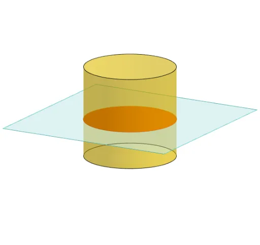
This example demonstrates slicing a cylinder at various angles and positions to observe the changes in cross-sectional shapes. It involves core mathematical concepts such as solid geometry, vectors, polygons, area calculation, trigonometric functions, and analytical geometry. Key GeoGebra commands used include Polygon, PointIn, Translate, Rotate, Cylinder, Plane, IntersectPath, OrthogonalLine, and Ends. Suitable for high school and above students studying solid geometry, vectors, and analytical geometry, or for mathematical teaching demonstrations.
GeoGebra Commands & Parameters
Polygon(B + (-2, -2), B + (2, -2), B + (2, 2), B + (-2, 2)) → poly3, e, f, g, iPointIn(poly3) → CTranslate((0, 0, 0), Vector[B, C]) → APolygon(A + (-4, -4), A + (4, -4), A + (4, 4), A + (-4, 4)) → poly1, a, b, c, dRotate(Rotate[Translate[poly1, Vector[A, A + (0, 0, h)]], (90° * s), A + (0, 0, h), yAxis], (90° * t), A, zAxis) → poly2Rotate(D, 120°, (0, 0, 0)) → EPolygon(D, E, 3, xOyPlane) → poly4, j, k, l, FCylinder((0, 0, 0), (0, 0, 4), 2) → m, e_1, f_1, oPointIn(poly2) → GPointIn(poly2) → HPointIn(poly2) → IPlane(G, I, H) → nIntersectPath(n, m) → poly6OrthogonalLine(A, n) → d_1Ends(m) → g_1, g_1_1
AI Drawing Prompt Reference
Draw a cylinder and create a rectangle on its surface. Then, rotate and move the rectangle at various angles and positions to observe the changes in cross-sectional shapes. Start by creating a rectangle, then translate and rotate it around the cylinder's central axis. Next, select three points on the rectangle to form a plane, and finally intersect this plane with the cylinder to display the cross-sectional shapes.
The prompt above was compiled from the original drawing commands and is for reference only.