
Prisms and Cylinders Geometric Demo
Loading the math board and drawing, please wait…
This example demonstrates the geometric construction and properties of prisms and cylinders. It involves core mathematical concepts such as solid geometry, vectors, trigonometric functions, and median values. GeoGebra commands and objects used include Sequence, Insert, Div, Segment, Polygon, and Centroid. Suitable for high school and above students for learning 3D geometry and understanding three-dimensional shapes.
GeoGebra Commands & Parameters
Sequence({{cos(((k * a) * t)), (-sin(((k * a) * t))), 0}, {sin(((k * a) * t)), cos(((k * a) * t)), 0}, {0, 0, 1}}, k, 0, N) → LiRaSequence({{cos((k * a)), sin((k * a)), 0}, {(-sin((k * a))), cos((k * a)), 0}, {0, 0, 1}}, k, 0, N) → LiRSequence(Element[({{l, 0, 0}} * Element[LiR, k]), 1], k, 1, N + 1) → V_0Sequence(Element[Element[RV_0, k], 1], k, 1, N + 1) → RV_xSequence(Element[Element[RV_0, k], 2], k, 1, N + 1) → RV_ySequence({Sum[RV_x, k], Sum[RV_y, k], 0}, k, 1, N + 1) → SumRVSequence(Element[({Element[V_0, k]} * Element[LiRa, k]), 1], k, 1, N) → VQSequence(Element[Element[VQ, k], 1], k, 1, N) → VQ_xSequence(Element[Element[VQ, k], 2], k, 1, N) → VQ_ySequence({Sum[VQ_x, k], Sum[VQ_y, k], 0}, k, 1, N) → SumVQSequence(Element[SumVQ, k] + {0, 0, (-1 * altezza)}, k, 1, N) → RSequence(Element[Element[V_0, k], 2], k, 1, N + 1) → V_{0y}Sequence(Element[Element[V_0, k], 1], k, 1, N + 1) → V_{0x}Sequence({Sum[V_{0x}, k], Sum[V_{0y}, k], 0}, k, 1, N + 1) → SumV_0Sequence(Element[SumV_0, k], k, 1, N + 1) → PInsert({Element[P, N]}, SumVQ, 1) → QDiv(N, 2) → MInsert({Element[P, N] + {0, 0, (-1 * altezza)}}, R, 1) → R1Sequence((Element[Element[(Q * Cav), k], 1], Element[Element[(Q * Cav), k], 2]), k, 1, N + 1) → PQSequence((Element[Element[(RP * Cav), k], 1], Element[Element[(RP * Cav), k], 2]), k, 1, N + 1) → PPSequence(Element[R, N] + Element[S_R, k], k, 1, N + 1) → SSequence((Element[Element[(R1 * Cav), k], 1], Element[Element[(R1 * Cav), k], 2]), k, 1, N + 1) → PRSequence((Element[Element[(S * Cav), k], 1], Element[Element[(S * Cav), k], 2]), k, 1, N + 1) → PSSequence(Segment[Element[PS, k], Element[PS, k + 1]], k, 1, N) → SpigoliSottoSequence(Segment[Element[PP, k], Element[PP, k + 1]], k, 1, N) → SpigoliSopraSequence(Polygon[Element[PQ, k], Element[PQ, k + 1], Element[PR, k + 1], Element[PR, k]], k, 1, N) → FacceLatSequence(Segment[Element[PQ, k], Element[PR, k]], k, 1, N + 1) → SpigoliLatSequence(Segment[Element[PS, k], Element[PS, k + 1]], k, 1, N) → p_{base}Sequence(Segment[Element[PR, k], Element[PR, k + 1]], k, 1, N + 1) → SpigoliLatSottoSegment(Element[PQ, 1], Element[PR, 1]) → hPolygon(PS) → poly2Centroid(poly2) → DPolygon(PP) → poly1Centroid(poly1) → A
AI Drawing Prompt Reference
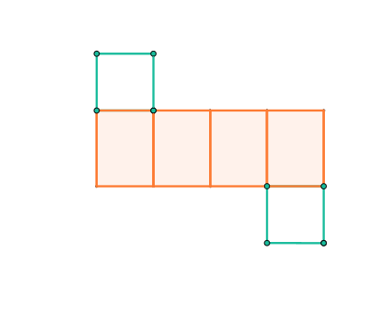
Draw a 3D prism. The prism has a polygonal base and a top face that are parallel and congruent. The lateral faces are rectangles perpendicular to the base. The construction order: first draw the base polygon, then the top polygon, then draw vertical lines connecting them, and finally draw all rectangular side faces. The figure should clearly show the geometric structure of the prism, including the base, top, and sides.
The prompt above was compiled from the original drawing commands and is for reference only.