
Cutting a Prism with an Interactive Plane
Loading the math board and drawing, please wait…
In collections
Cutting solids by a plane
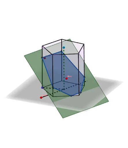
This example demonstrates how to cut a prism with an interactive plane. Key mathematical concepts include the intersection of a plane and a prism in solid geometry. Using GeoGebra commands such as Point, Cube, Line, Intersect, etc., the various faces of the prism and the intersection lines after cutting can be constructed. Suitable for high school geometry education or self-study.
GeoGebra Commands & Parameters
Point(Circle[B, Distance[A, B], Segment[A, B]]) → CCube(A, B, C) → a, D, faceCDHG, faceEFGH, arêteAD, arêteAB, arêteBC, arêteCD, arêteAE, arêteDH, arêteEH, arêteEF, E, arêteBF, arêteFG, arêteCG, arêteGH, F, G, H, faceABCD, faceADHE, faceABFE, faceBCGFMidpoint(C, A) → IMidpoint(F, H) → JLine(J, I) → fCircle(I, Distance[A, B], f) → cPoint(c) → KMidpoint(F, C) → MMirror(K, I) → K'Line(K', K) → gCircle(I, (1.2 * Distance[A, B]), g) → dPoint(d) → LPlane(L, K, K') → pCircle(K', L, K) → eCenter(e) → NOrthogonalLine(N, p) → hPoint(h) → OVector(I, O) → uTranslate(p, u) → p'Segment(K', K) → bLine(L, b) → f_1Point(arêteEF) → D_1OrthogonalLine(K, p) → h_1Plane(K', h_1) → p_1OrthogonalLine(K, p_1) → k_1Line(K', k_1) → l_1Intersect(f_1, l_1) → E_1Intersect(k_1, f_1) → F_1Mirror(F_1, K) → G_1Mirror(E_1, K') → H_1Polygon(F_1, E_1, H_1, G_1) → q2, m_1, e_1, n_1, q_1Translate(q2, u) → q2'Circle(I, Distance[I, A], f) → qPoint(f) → SSegment(A, I) → iSegment(I, S) → jSequence(Rotate[A, i, f], i, 0, (2 * π), (2 * π / Sides)) → l1Polygon(l1) → poly1Sequence(Rotate[A + (0, 0, Distance[I, S]), i, f], i, 0, (2 * π), (2 * π / Sides)) → l1bPrism(poly1, (-Distance[I, S])) → o, R_2, face45, face46, face47, face48, face43, face49, arête42, arête43, arête44, arête45, S_2, arête46, arête47, arête48, arête49, arête51, arête52, arête53, arête54, arête55, arête50, T_2, U_2, V_2, W_2, Z_2, face42, face44IntersectPath(p', o) → poly2, P, l, m, n, r, s, t, c_1, Q, R, T, Z, A_1, B_1, P_1, kSequence(Segment[Element[l1, i], Element[l1b, i]], i, 1, Length[l1]) → l3Polygon(l1) → poly3Polygon(l1b) → poly4
AI Drawing Prompt Reference
Draw a cube and then cut it with a movable plane to show the intersection lines and new polygonal faces. First, create the cube's faces and edges, then define a plane and move it to cut the cube, and finally display the intersection lines and new polygonal faces.
The prompt above was compiled from the original drawing commands and is for reference only.