
Controlling Cube Cross Section
Loading the math board and drawing, please wait…
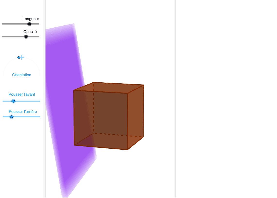
This example demonstrates how to dynamically control the cross-section shape of a cube by adjusting parameters. It involves core mathematical concepts such as solid geometry, coordinate geometry, trigonometry, and geometric transformations. Key GeoGebra commands and objects used include Semicircle, Point, Prism, Line, OrthogonalLine, OrthogonalPlane, DynamicCoordinates, If, Rotate, and IntersectPath. Suitable for high school and above students to explore properties and variations of solid geometry.
GeoGebra Commands & Parameters
Semicircle(N, M) → gPoint(g) → KPoint(g, 0.5) → milPrism(A, B, C, D, E) → Pr, F, arêteAB, arêteBC, arêteCD, arêteAD, arêteAE, arêteBF, arêteCG, arêteDH, arêteEF, arêteFG, G, arêteGH, arêteEH, H, faceABCD, faceABFE, faceBCGF, faceCDHG, faceADHE, faceEFGHLine(PA, PB) → DSOrthogonalLine(PA, DS, xOyPlane) → PEOrthogonalPlane(PA, PE) → sectionDynamicCoordinates(K, If[Distance[mil, K] < 0.1, x(mil), x(K)], If[Distance[mil, K] < 0.1, y(mil), y(K)]) → PIf(P ≟ mil, 0*°, (((0.5 - PathParameter[K]) * 180))°) → αRotate(section, α, DS) → PlanInclinéIntersectPath(PlanIncliné, Pr) → polygone, Q, k, a, b, R, S, T, I, J, h, i, j
AI Drawing Prompt Reference
Draw a cube and construct a dynamic inclined cross-section inside it. Start by creating a semicircle on a segment, place a movable point on it, and mark its midpoint as a reference. From a vertex of the cube, draw a line perpendicular to the base, then create a plane through that vertex perpendicular to the line as the initial section. Rotate this plane around the line, with the rotation angle determined by the position of the point on the semicircle, so that the plane intersects the cube to form a polygon. Adjust the point on the semicircle to observe how the cross-section shape changes.
The prompt above was compiled from the original drawing commands and is for reference only.