
Projections from 3D Object to 2D Plane
Loading the math board and drawing, please wait…
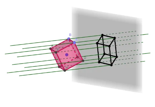
① This example demonstrates how to project a 3D object (such as a sphere, a cube, and points, lines, faces on it) onto a 2D plane via orthogonal projection, visualizing the mapping from 3D space to 2D. ② Core mathematical concepts include 3D geometry, orthogonal projection, intersections of solids and planes (e.g., a sphere intersecting a plane yields a conic section), intersections of lines and planes, and the spatial relationships among faces, edges, and vertices of a cube. ③ Construction details: using GeoGebra commands such as Sphere to create a sphere, PointIn to pick a point on the sphere, IntersectConic to find the conic intersection of the sphere and a plane, OrthogonalPlane to construct an orthogonal plane, Intersect to find intersection points, Cube to build a cube, Join to connect segments, Sequence to generate lists, SelectedIndex and Textfield for interactive control. Objects include size, c, a, A, e, g, B, i, j, h, k, C, C_2, l1a, l, D, E, F, G, H, the six faces of the cube (faceABCD, faceADHE, etc.) and twelve edges (edgeAD, edgeAB, etc.). ④ Suitable for high school or early college students learning solid geometry, spatial visualization, and projection transformations; also useful for math lab activities or teacher demonstrations of 3D-to-2D visualization.
GeoGebra Commands & Parameters
Sphere(c, (size * sqrt(3) / 2)) → aPointIn(a) → ASphere(A, size) → eIntersectConic(a, e) → gPoint(g) → BLine(A, B) → iOrthogonalPlane(B, i) → jSphere(B, A) → hIntersectConic(a, h) → kIntersect(j, k) → C, C_2Cube(A, B, C) → l, D, faceCDHG, faceEFGH, edgeAD, edgeAB, edgeBC, edgeCD, edgeAE, edgeDH, edgeEH, edgeEF, E, edgeBF, edgeFG, edgeCG, edgeGH, F, G, H, faceABCD, faceADHE, faceABFE, faceBCGFLine(c, A) → fJoin({Sequence[l1a(i), i, 1, 3], l1b}) → l1Sequence(Line[Element[l1, i], vz], i, 1, Length[l1]) → l2Sequence(Intersect[Element[l2, i], xOyPlane], i, 1, Length[l2]) → l3Sequence(Segment[Element[l3, Element[l4, (2 * i) - 1]], Element[l3, Element[l4, (2 * i)]]], i, 1, Length[l4] / 2) → l5SelectedIndex(l6) → indexPoint(zAxis) → eyeSequence(Ray[eye, Element[l1, i]], i, 1, Length[l1]) → l7Sequence(Intersect[Element[l7, i], xOyPlane], i, 1, Length[l2]) → l8Sequence(Segment[Element[l8, Element[l4, (2 * i) - 1]], Element[l8, Element[l4, (2 * i)]]], i, 1, Length[l4] / 2) → l9Point(zAxis) → ecTextfield(eyeDistance) → InputBox1Sequence(Ray[left, Element[l1, i]], i, 1, Length[l1]) → l10Sequence(Intersect[Element[l10, i], xOyPlane], i, 1, Length[l2]) → l11Sequence(Segment[Element[l11, Element[l4, (2 * i) - 1]], Element[l11, Element[l4, (2 * i)]]], i, 1, Length[l4] / 2) → l12Sequence(Ray[right, Element[l1, i]], i, 1, Length[l1]) → l13Sequence(Intersect[Element[l13, i], xOyPlane], i, 1, Length[l13]) → l14Sequence(Segment[Element[l14, Element[l4, (2 * i) - 1]], Element[l14, Element[l4, (2 * i)]]], i, 1, Length[l4] / 2) → l15Textfield(decX) → InputBox2Textfield(decY) → InputBox3Sequence(Line[Element[l1, i], vOblique], i, 1, Length[l1]) → l16Sequence(Intersect[Element[l16, i], xOyPlane], i, 1, Length[l16]) → l17Sequence(Segment[Element[l17, Element[l4, (2 * i) - 1]], Element[l17, Element[l4, (2 * i)]]], i, 1, Length[l4] / 2) → l18
AI Drawing Prompt Reference
Draw a sphere, then select a point A on the sphere and draw a circle e with A as the center and the same radius as the sphere. The sphere and circle e intersect to form an ellipse g, and select a point B on the ellipse. Draw a line i through points A and B, and construct a plane j perpendicular to line i. The sphere with center B and radius AB intersects with plane j to form another ellipse h, and the ellipses g and h intersect to form two lines C and C_2. Then, construct a cube with points A and B as vertices, and connect the faces and edges of the cube. Finally, draw a series of lines parallel to the z-axis through points A and B, observe their projections on the xOy plane, and adjust the viewing angle to see the cube's projection changes from different perspectives.
The prompt above was compiled from the original drawing commands and is for reference only.