
Vector & Mirror-Symmetry Geometric Construction for a Logo-Style Mark
Loading the math board and drawing, please wait…
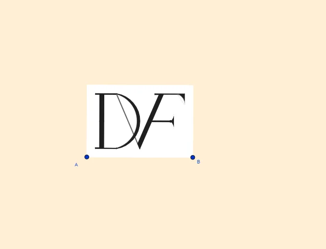
This GeoGebra example demonstrates how to construct a logo-like figure by combining geometric building blocks and symmetry. It highlights 2D vector representation, constructions related to angle bisectors, orthogonality (perpendicular lines/vectors), mirror (reflection) transformations, and precise placement using intersections. The construction workflow uses LineBisector to obtain bisectors, Vector and OrthogonalVector to define directions, and OrthogonalLine/Line to enforce perpendicular relationships. Mirror is then applied to generate the symmetric counterpart. Key points are determined with Intersect, while Polygon and Segment organize straight boundary parts. Finally, CircumcircleArc and CircleArc create smooth curved edges so the overall outline becomes continuous. Suitable for secondary school geometry extension, transformation-based geometry lessons, and students learning geometric construction in dynamic geometry software.
GeoGebra Commands & Parameters
LineBisector(A, B) → mVector(A, B) → uOrthogonalVector(u) → vLineBisector(A_1, A) → lLine(A, B) → sOrthogonalLine(D, s) → iMirror(i, m) → i'OrthogonalLine(A, s) → bOrthogonalLine(A_1, b) → rOrthogonalLine(F, b) → fMirror(f, l) → f'Intersect(i', f') → PIntersect(i, f') → EMirror(I, m) → I'OrthogonalLine(M, r) → nLine(L, n) → pLine(I', p) → qLine(U, q) → aOrthogonalLine(N, b) → jIntersect(a, j) → C_1LineBisector(C_1, Q) → g_2Intersect(g_2, a) → S_1Intersect(q, g_2) → T_1Vector(S_1, T_1) → u_1Intersect(m, l) → KIntersect(i, l) → JIntersect(m, f') → SMirror(f, l) → f'_1OrthogonalLine(G, f'_1) → hOrthogonalLine(B, u, xOyPlane) → gIntersect(g, r) → CMirror(F, l) → F'Polygon(A_1, C, B, A) → c4, a_1, c_3, b_2, a_2OrthogonalLine(H, f'_1) → kIntersect(i', f) → J_1Intersect(f, m) → D_1Intersect(h, j) → OMirror(R, l) → R'Mirror(T, l) → T'Intersect(n, j) → VIntersect(p, j) → WIntersect(q, j) → ZLine(I, k) → tIntersect(t, j) → B_1Line(T, l) → cLine(R', c) → eLine(T', c) → f_1Line(R, c) → h_1Intersect(h, l) → E_1Intersect(k, l) → H_1Intersect(k, j) → I_1Polygon(E, I, B_1, I_1, H_1, E_1, O, N) → poly1, e_3, i_1, b_1, d, g_1, j_1, o, n_1Segment(B_1, D_1) → k_1Intersect(f, t) → K_1CircumcircleArc(I, K, K_1) → c_1Mirror(B_1, l) → L_1CircumcircleArc(B_1, M_1, L_1) → d_1Mirror(E, l) → E'Mirror(I, l) → I'_1Mirror(B_1, l) → N_1Mirror(I_1, l) → O_1Mirror(H_1, l) → P_1Mirror(E_1, l) → Q_1Mirror(O, l) → O'Mirror(N, l) → N'Polygon(E', I'_1, N_1, O_1, P_1, Q_1, O', N') → poly1', e', i'_1, l_1, o_1, p_1, q_1, o', n'Line(D_1, Z) → m_1Line(W, m_1) → r_1Intersect(r_1, k_1) → R_1Polygon(D_1, R_1, W, V, M, P, Q, C_1, Z) → poly2, s_1, t_1, w, v_1, m_2, p_2, q_2, f_2, z_1CircleArc(U_1, Q, C_1) → c_2Intersect(m_1, e) → W_1Intersect(m_1, h_1) → Z_1OrthogonalLine(U_1, j) → h_2Intersect(h_2, c) → F_1Intersect(f_1, h_2) → G_1OrthogonalLine(V_1, f) → i_2Intersect(i_2, h_1) → A_2Intersect(i_2, e) → B_2Polygon(W_1, B_2, G_1, F_1, A_2, Z_1) → poly3, w_1, j_2, k_2, l_2, n_2, r_2LineBisector(A_2, F_1) → s_2Intersect(s_2, q) → C_2CircleArc(C_2, A_2, F_1) → d_2Segment(B_1, N_1) → f_3Segment(C_1, Q) → g_3Segment(F_1, A_2) → h_3Segment(B_2, G_1) → i_3Mirror(d_2, l) → t_2Intersect(i_2, l) → D_2Intersect(a, j) → E_2
AI Drawing Prompt Reference
On a 2D plane, construct a logo-like geometric figure made from straight and mirrored parts. First determine two main direction lines using an angle-bisector type construction from given endpoints, then create vectors and corresponding perpendicular directions to draw several constraint lines. Use intersections of these perpendicular and direction lines to locate the main corner points. Reflect one set of the constructed lines across the appropriate symmetry lines to obtain the corresponding mirrored lines and points. Connect the resulting intersection points to form a closed polygonal outline, and replace selected straight edges with smooth circular arcs so the overall boundary becomes continuous. The final mark should exhibit mirror symmetry.
The prompt above was compiled from the original drawing commands and is for reference only.