
Unit Circle Diagram
Loading the math board and drawing, please wait…
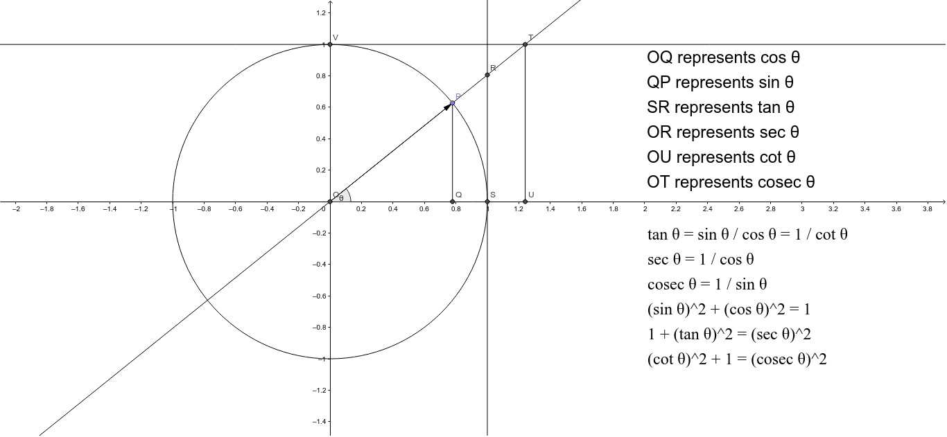
The unit circle diagram is a fundamental concept in coordinate geometry, illustrating the relationship between points on a circle of radius 1 and their corresponding angles. Key mathematical concepts include the equation of a circle, the conversion between angles and coordinates, and the positioning of points in a coordinate system. Construction involves using GeoGebra commands such as Circle, Point, Angle, and Line to create the unit circle and mark angles. This example is suitable for middle or high school mathematics education to understand basic trigonometric concepts and coordinate geometry.
GeoGebra Commands & Parameters
Intersect(xAxis, yAxis) → OCircle(O, 1) → dPoint(d) → PLine(O, P) → aIntersect(a, c) → RIntersect(a, b) → TVector(O, P) → uSegment(Q, P) → eIntersect(d, c, 1) → SIntersect(d, b, 1) → VSegment(U, T) → fAngle(S, O, P) → θ
AI Drawing Prompt Reference
Draw a unit circle centered at the origin with a radius of 1. Select a point P on the circle and draw a line a from the origin to P. Line a intersects the x-axis at point R and the y-axis at point T. Draw a vector u from the origin to P, and a line segment e from P to the origin. Select two points S and V on the unit circle such that the angles formed with the origin are 90 degrees and 180 degrees, respectively. Draw a line segment f connecting points S and T, and label the angle θ.
The prompt above was compiled from the original drawing commands and is for reference only.