
Slanted vs. Spanned Planes: Building 3D Geometry from Points
Loading the math board and drawing, please wait…
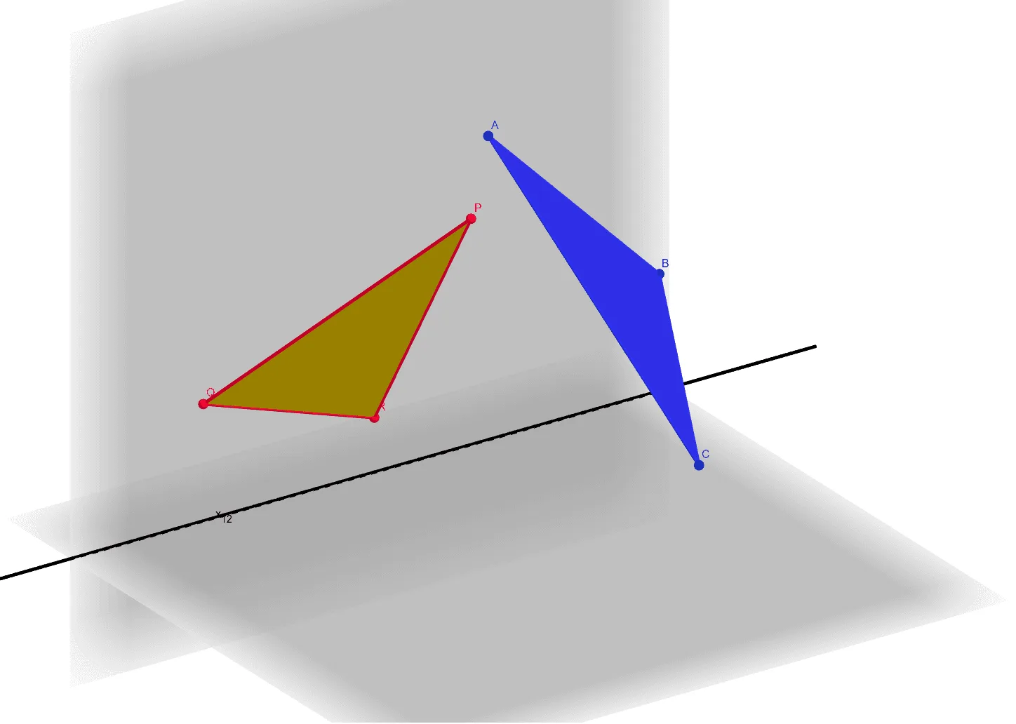
This GeoGebra example compares a slanted plane with a plane that is “spanned” by a specified geometric relationship, illustrating how the position and orientation of a plane change under different constructions while still relating to the same underlying spatial point structure. It highlights key ideas such as: how three non-collinear points determine a plane, relative placement of lines and planes in 3D space, and the “span” concept (a plane generated by given points/vectors). Construction-wise, it uses fundamental GeoGebra commands to create and connect geometry: Point and Plane to define spatial control points and their corresponding planes; Polygon to form visible plane regions/face patches; and Line to link points and provide directional or reference structure. The scene is organized around many labeled objects (e.g., control points and multiple auxiliary entities like t1–t4, p, q, and other construction variables) that support the comparison between slanted versus spanned configurations. Suitable for upper-secondary students and early university learners studying solid geometry and coordinate/3D reasoning, and for interactive classroom demonstrations or explorations in GeoGebra.
GeoGebra Commands & Parameters
Point(yAxis) → APoint(zAxis) → BPoint(yAxis) → CPlane(A, B, C) → pPoint(xAxis) → DPlane(A, D, C) → qPolygon(E, F, G) → t1, g, e, fPolygon(J, I, H) → t2, h, j, iLine(A, C) → kPolygon(M, K, L) → t3, l, m, k_1Polygon(N, P, O) → t4, o, n, p_1
AI Drawing Prompt Reference
Draw two planes in 3D space, one slanted and one generated by a specific point relationship, showing how their positions and orientations change under different constructions while still relating to the same underlying spatial point structure. Use points and lines to define the positions of spatial control points and their corresponding planes, polygons to form visible plane regions, and connect points with lines to provide directional or reference structures. The scene includes many labeled objects, such as control points and multiple auxiliary entities (like t1-t4, p, q), to support the comparison between the slanted and spanned configurations.
The prompt above was compiled from the original drawing commands and is for reference only.