
Cube and Shadows with a Slanted Image Plane
Loading the math board and drawing, please wait…
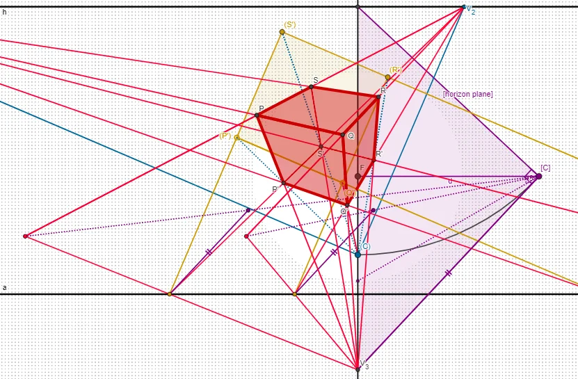
This example demonstrates a cube and its projection in a slanted image plane. Key mathematical concepts include solid geometry and projection transformations. Using GeoGebra commands such as OrthogonalLine, Circle, Intersect, etc., the construction of the cube and its projection is achieved. Suitable for high school or university solid geometry courses.
GeoGebra Commands & Parameters
OrthogonalLine(F, eq1) → iCircle(F, d) → cIntersect(c, i, 2) → ASegment(F, A) → jIntersect(h, eq1) → BSegment(B, A) → kOrthogonalLine(A, k) → lIntersect(eq1, l) → V_3Segment(V_3, A) → mAngle(B, A, V_3) → βPolygon(B, A, V_3) → t1, i_5, b_6, a_6Circle(B, A) → eRotate(F, 30°, A) → F'Angle(F, A, F') → αLine(A, F') → f_5Intersect(eq1, f_5) → G_1Segment(G_1, A) → g_5Circle(F, G_1) → c_5Intersect(e, eq1, 2) → CCircleArc(B, C, A) → pPoint(Circle[D, a]) → ESegment(D, E) → nPolygon(D, E, 4) → poligon1, q, r, s, t, G, HLine(C, n) → bLine(C, r) → g_1Intersect(h, g_1) → V_2Segment(C, V_2) → h_1Intersect(h, b) → V_1Segment(C, V_1) → i_1Line(G, E) → j_1Line(H, D) → k_1Line(E, D) → l_1Line(H, G) → m_1Intersect(f_1, k_1) → KSegment(K, D) → n_1Intersect(f_1, j_1) → LSegment(L, E) → p_1Intersect(f_1, l_1) → MSegment(M, E) → q_1Intersect(f_1, m_1) → NSegment(G, N) → r_1Line(L, V_2) → s_1Line(K, V_2) → t_1Line(N, V_1) → a_1Line(M, V_1) → b_1Intersect(t_1, b_1) → OIntersect(t_1, a_1) → PIntersect(s_1, a_1) → QIntersect(s_1, b_1) → RSegment(K, O) → c_1Segment(O, P) → d_1Segment(P, V_2) → e_1Segment(L, R) → f_2Segment(R, Q) → g_2Segment(Q, V_2) → h_2Segment(M, R) → i_2Segment(R, O) → j_2Segment(O, V_1) → k_2Segment(N, Q) → l_2Segment(P, V_2) → i_6Segment(Q, P) → m_2Segment(P, V_1) → n_2Polygon(O, P, Q, R) → q1, o, p_5, q_5, r_5Segment(D, C) → p_2Segment(O, D) → r_2Segment(E, R) → s_2Segment(E, C) → t_2Segment(H, C) → a_2Segment(H, P) → b_2Segment(G, C) → c_2Segment(G, Q) → d_2Line(K, m) → e_2Line(L, m) → f_3Circle(K, a) → c_3Circle(L, a) → d_3Intersect(c_3, e_2, 2) → SSegment(S, K) → g_3Intersect(d_3, f_3, 2) → TSegment(T, L) → h_3Segment(A, V_3) → gLine(V_3, L) → i_3Line(V_3, K) → j_3Line(A, T) → k_3Line(A, S) → l_3Intersect(i_3, k_3) → USegment(L, U) → m_3Segment(L, V_3) → f_4Intersect(j_3, l_3) → VSegment(K, V) → n_3Segment(K, V_3) → g_4Segment(A, U) → p_3Segment(A, V) → q_3Intersect(n_3, q_3) → WIntersect(m_3, p_3) → ZLine(Z, V_2) → r_3Line(V_2, W) → s_3Line(O, V_3) → t_3Line(R, V_3) → a_3Line(Q, V_3) → b_3Line(P, V_3) → e_3Segment(W, V_2) → h_4Intersect(s_3, t_3) → A_1Segment(A_1, V_3) → t_4Segment(A_1, V_2) → e_5Intersect(s_3, e_3) → B_1Segment(A_1, B_1) → i_4Segment(B_1, V_3) → a_4Segment(A_1, W) → j_4Segment(Z, V_2) → n_4Intersect(s_3, e_3) → C_1Segment(V_2, C_1) → k_4Intersect(s_3, t_3) → D_1Segment(C_1, D_1) → l_4Segment(D_1, W) → m_4Segment(E, C) → q_2Intersect(r_3, a_3) → E_1Segment(E_1, V_3) → r_4Segment(Z, E_1) → p_4Intersect(r_3, b_3) → F_1Segment(F_1, V_3) → s_4Segment(F_1, V_2) → g_6Segment(E_1, F_1) → q_4Segment(E_1, A_1) → b_4Segment(A_1, V_1) → c_4Segment(F_1, B_1) → d_4Segment(B_1, V_1) → e_4Polygon(P, B_1, F_1, Q) → q2, p_6, h_5, f_{6}, q_6Polygon(P, O, A_1, B_1) → q3, p_7, o_1, j_5, k_5Polygon(A_1, E_1, R, O) → q4, l_5, m_5, r_6, o_2Polygon(E_1, F_1, Q, R) → q5, n_5, s_5, q_7, r_7Polygon(A_1, B_1, F_1, E_1) → q6, t_5, a_5, b_5, d_5Line(V_3, I) → j_6Intersect(h, j_6) → JSegment(V_3, J) → k_6Segment(R, J) → l_6Segment(E_1, I) → m_6Intersect(l_6, m_6) → H_1Segment(Q, J) → n_6Segment(F_1, I) → s_6Intersect(n_6, s_6) → I_1Segment(H_1, V_2) → t_6Segment(P, J) → c_6Segment(B_1, I) → d_6Intersect(c_6, d_6) → J_1Segment(I_1, V_1) → e_6Intersect(s_4, e_6) → K_1Segment(R, H_1) → m_7Segment(J_1, P) → n_7Polygon(K_1, I_1, H_1, R, Q) → poligon2, f_7, g_7, h_7, r_8, q_8Intersect(r_8, q_8) → L_1Intersect(h_7, r_8) → M_1Polygon(F_1, L_1, M_1, E_1) → q7, i_7, j_7, k_7, l_7
AI Drawing Prompt Reference
Draw a cube and its shadow on a slanted image plane. Start by defining a slanted plane and a point on it as the projection center. Through this point, draw a line perpendicular to the plane, intersecting a circle to get a projection point. Connect the center to this pointhol, then intersect with the plane to form a triangle. Next, rotate the center point by 30 degrees to create an angle, and draw a line through the rotated point intersecting the plane to get another projection point. Then construct a square as the base of the cube, and connect its vertices to form the cube. Finally, from each vertex of the cube, draw lines to the projection plane, find their intersections with the plane, and connect these intersection points to outline the cube's projected shape on the slanted plane, including the quadrilateral formed by these intersections.
The prompt above was compiled from the original drawing commands and is for reference only.