
Shadow of a Cube: Geometric Construction and Coordinate Transformation
Loading the math board and drawing, please wait…
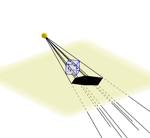
This example demonstrates the shadow projection of a cube in different coordinate systems, involving mathematical concepts such as coordinate geometry, geometric transformations, and solid geometry. The construction uses GeoGebra commands like Rotate, Intersect, Translate, and Point, along with Vector objects to achieve the projection. It is suitable for students in middle school and above to practice geometric transformations and solid geometry.
GeoGebra Commands & Parameters
Rotate(P, α, xAxis) → P'Rotate(P', β, yAxis) → P''Rotate(P'', γ, zAxis) → P'''Intersect(xAxis, zAxis) → OPoint(zAxis) → QVector(O, Q) → uTranslate(P''', u) → l1Point(l1) → IPoint(l1) → JPoint(l1) → KPoint(l1) → LPolygon(I, J, K, L) → q1, i, j, k, lPoint(l1) → MPoint(l1) → NPolygon(M, L, I, N) → q2, m, l_1, i_1, nPoint(l1) → RPoint(l1) → SPolygon(N, R, S, M) → q3, n_1, r, s, m_1Point(l1) → TPoint(l1) → UPolygon(S, T, U, R) → q4, s_1, t, u_1, r_1Point(l1) → VPolygon(M, V, T, S) → q5, m_2, v, t_1, s_2Point(l1) → WPolygon(N, W, U, R) → q6, n_2, w, u_2, r_2Point(yAxis) → ZPoint(xAxis) → A_1Point(yAxis) → B_1Plane(Z, A_1, B_1) → pPoint(v) → D_1Ray(C_1, D_1) → fPoint(l1) → E_1Ray(C_1, E_1) → gPoint(l1) → F_1Ray(C_1, F_1) → hPoint(l1) → G_1Ray(C_1, G_1) → qPoint(t_1) → H_1Ray(C_1, H_1) → aPoint(u_2) → I_1Ray(C_1, I_1) → bPoint(m_1) → J_1Ray(C_1, J_1) → cPoint(l1) → K_1Ray(C_1, K_1) → dIntersect(h, p) → L_1Intersect(c, p) → M_1Intersect(q, p) → N_1Intersect(d, p) → O_1Intersect(g, p) → P_1Intersect(b, p) → Q_1Intersect(f, p) → R_1Intersect(a, p) → S_1Polygon(S_1, P_1, R_1) → t1, e, f_1, p_1Polygon(N_1, R_1, S_1) → t2, g_1, h_1, j_1Polygon(M_1, Q_1, L_1) → t3, k_1, q_1, a_1Polygon(Q_1, P_1, S_1) → t4, b_1, c_1, d_1Polygon(L_1, S_1, Q_1) → t5, e_1, f_2, g_2Polygon(N_1, S_1, L_1) → t6, h_2, i_2, j_2Polygon(M_1, L_1, N_1) → t7, k_2, l_2, p_2Polygon(Q_1, L_1, P_1) → t8, q_2, t_2, a_2Polygon(O_1, Q_1, M_1) → t9, b_2, o_1, c_2Polygon(O_1, S_1, Q_1) → t10, d_2, e_2, f_3Polygon(M_1, N_1, O_1) → t11, g_3, h_3, i_3Polygon(S_1, O_1, N_1) → t12, j_3, k_3, l_3
AI Drawing Prompt Reference
Draw a geometric diagram showing the shadow projection of a cube. Include a three-dimensional coordinate system with x-axis, y-axis, and z-axis. Show a cube composed of multiple polygonal faces. Add a projection plane determined by three points. Place a light source on one side of the cube, and draw rays from this light source through the cube's vertices extending to the projection plane, creating intersection points on the plane. Connect these intersection points to form the shadow outline of the cube on the plane, demonstrating the geometric relationship between the light source, cube, projection plane, and shadow.
The prompt above was compiled from the original drawing commands and is for reference only.