
Resultant Force of Two Parallel Forces
Loading the math board and drawing, please wait…
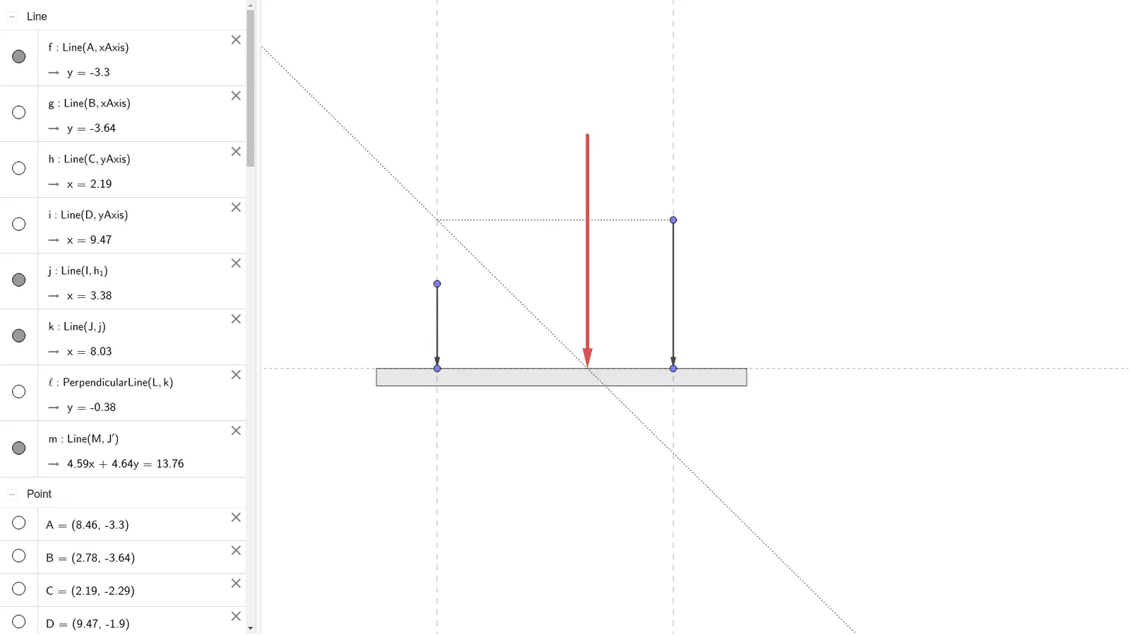
This GeoGebra example dynamically demonstrates the vector composition of two parallel forces, showing how the resultant force's magnitude, direction, and point of application are determined by the components. The core mathematical concept is vector addition for parallel force systems, involving the parallelogram law or collinear vector superposition. Construction highlights: using Line and Intersect to define lines of action and intersection points, Vector to represent component and resultant forces, OrthogonalLine and Translate to shift forces parallel, Polygon and Segment for auxiliary shapes, and Point/Slider objects to interactively adjust force magnitudes and directions. This example is ideal for high school physics or mathematics vector lessons, helping students grasp that the resultant of parallel forces equals the algebraic sum of components with same or opposite directions, and how the point of application relates to moment arms. It also serves as an introductory tool for university statics.
GeoGebra Commands & Parameters
Line(A, xAxis) → fLine(B, xAxis) → gLine(C, yAxis) → hLine(D, yAxis) → iIntersect(f, h) → EIntersect(f, i) → FIntersect(g, i) → GIntersect(g, h) → HPolygon(E, F, G, H) → c1, e, f_1, g_1, h_1Point(e) → IPoint(e) → JLine(I, h_1) → jLine(J, j) → kPoint(j) → KVector(K, I) → uPoint(k) → LVector(L, J) → vOrthogonalLine(L, k) → lTranslate(J, u) → J'Vector(J, J') → wIntersect(j, l) → MLine(M, J') → mTranslate(N, v) → N'Vector(N, N') → aTranslate(N', u) → N''Vector(N', N'') → bIntersect(f, m) → OVector(N'', N) → cTranslate(O, c) → O'Vector(O, O') → dVector(O', O) → nSegment(M, L) → p
AI Drawing Prompt Reference
Draw the resultant force of two parallel forces. First, draw two parallel lines f and g, then draw two perpendicular lines h and i on the x-axis and y-axis, and find intersection points E, F, G, and H to form quadrilateral c1. Next, draw lines j and k to determine points I, J, K, and L, representing forces u and v. Through rotation and translation, obtain forces w and a, then use point M and N to get forces b and d. Finally, connect M and L to get segment p, indicating the direction of the resultant force.
The prompt above was compiled from the original drawing commands and is for reference only.