
Radians in Unit Circle by Rose Neal
Loading the math board and drawing, please wait…
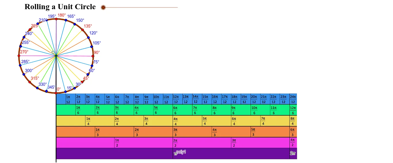
This interactive GeoGebra example visualizes the concept of radians within the unit circle, dynamically linking the rotation of a radius to the arc length it subtends. It demonstrates how an angle in radians equals the ratio of arc length to radius, making the fundamental connection between angle measure and circular geometry explicit. Core mathematical concepts include radian measure, unit circle, central angles, arc length, and the basis for trigonometric functions. The construction employs commands such as Circle, Point, Segment, Rotate, Angle, CircleArc, Vector, Translate, Mirror, and text objects to display the radian value. Suitable for high school or introductory college students learning trigonometry and angle conversion, this example serves as an effective teaching aid for classroom demonstrations or self-paced exploration of angular measurement.
GeoGebra Commands & Parameters
Line(A, B) → aLine(C, D) → bCircle(E, 2) → cOrthogonalLine(E, a) → dIntersect(d, a) → FSegment(A, F) → eRotate(F, (-(180 * e / 6.28))°, E) → F'Angle(F', E, F) → αCircleArc(E, F, F') → fVector(E, F') → uRotate(F', 3.141592653589793, E) → F''_1Vector(P, Q) → vTranslate(Q, v) → Q'Vector(Q, Q') → wTranslate(Q', w) → Q''Translate(Q'', w) → Q'''Translate(Q''', w) → RTranslate(R, w) → R'Vector(Q', Q'') → zVector(Q'', Q''') → mVector(Q''', R) → nVector(R, R') → pVector(P, R') → qRotate(F', 0.7853981633974483, E) → F''Angle(F', E, F'') → βRotate(F', 0.2617993877991494, E) → F''_2Angle(F', E, F''_2) → γRotate(F', 0.5235987755982988, E) → F''_3Angle(F', E, F''_3) → δRotate(F', 1.0471975511965976, E) → F''_4Angle(F', E, F''_4) → εRotate(F', 1.3089969389957472, E) → F''_5Angle(F', E, F''_5) → ζRotate(F', 1.5707963267948966, E) → F''_6Angle(F', E, F''_6) → ηRotate(F', 1.8325957145940461, E) → F''_7Angle(F', E, F''_7) → θRotate(F', 2.0943951023931953, E) → F''_8Angle(F', E, F''_8) → ιRotate(F''_8, 0.2617993877991494, E) → UAngle(F''_8, E, U) → κRotate(U, 0.2617993877991494, E) → U'Angle(U, E, U') → λRotate(U', 0.2617993877991494, E) → U''Angle(U', E, U'') → μRotate(U'', 0.2617993877991494, E) → U'''Angle(U'', E, U''') → νRotate(U''', 0.2617993877991494, E) → VAngle(U''', E, V) → ξRotate(V, 0.2617993877991494, E) → V'Angle(V, E, V') → οRotate(V', 0.2617993877991494, E) → V''Angle(V', E, V'') → ρRotate(V'', 0.2617993877991494, E) → V'''Angle(V'', E, V''') → σRotate(V''', 0.2617993877991494, E) → WAngle(V''', E, W) → τRotate(W, 0.2617993877991494, E) → W'Angle(W, E, W') → υRotate(W', 0.2617993877991494, E) → W''Angle(W', E, W'') → ϕRotate(W'', 0.2617993877991494, E) → W'''Angle(W'', E, W''') → χRotate(W''', 0.2617993877991494, E) → ZAngle(W''', E, Z) → ψRotate(Z, 0.2617993877991494, E) → Z'Angle(Z, E, Z') → ωRotate(Z', 0.2617993877991494, E) → Z''Angle(Z', E, Z'') → α_1Mirror(A_1, J) → B_1Line(B_1, a) → gOrthogonalLine(T, g) → hIntersect(g, h) → C_1Segment(J, B_1) → iSegment(B_1, C_1) → jSegment(C_1, T) → kSegment(T, J) → lPoint(l) → D_1OrthogonalLine(D_1, j) → rIntersect(j, r) → E_1Segment(D_1, E_1) → sOrthogonalLine(G, a) → tIntersect(t, j) → F_1Intersect(t, l) → G_1Segment(F_1, G_1) → a_1Polygon(B_1, J, T, C_1) → poly1, b_1, j_1, t_1, c_1OrthogonalLine(E, a) → d_1Point(d_1) → H_1Segment(H_1, F''_2) → e_1Segment(H_1, F''_3) → f_1Segment(H_1, F'') → g_1Segment(H_1, F''_4) → h_1Segment(H_1, F''_5) → i_1Segment(H_1, F''_6) → k_1Segment(H_1, F''_7) → l_1Segment(H_1, F''_8) → m_1Segment(H_1, U) → n_1Segment(H_1, U') → p_1Segment(H_1, U'') → q_1Point(d_1) → I_1Segment(H_1, I_1) → r_1Segment(H_1, V) → s_1Segment(H_1, V') → a_2Segment(H_1, V'') → b_2Segment(H_1, V''') → c_2Segment(H_1, W) → d_2Segment(H_1, W') → e_2Segment(H_1, W'') → f_2Segment(H_1, W''') → g_2Segment(H_1, Z) → h_2Segment(H_1, Z') → i_2Segment(H_1, Z'') → j_2Point(d_1) → J_1Ray(H_1, J_1) → k_2Point(k_2) → K_1Segment(H_1, K_1) → l_2Segment(F', H_1) → m_2Segment(H_1, U''') → n_2Ray(H_1, K_1) → p_2Intersect(e_1, f_1) → OPoint(m_2) → L_1Point(k_1) → M_1Point(n_2) → N_1Point(e_2) → P_1Point(g_1) → Q_1Point(n_1) → R_1Point(b_2) → S_1Point(h_2) → T_1Point(e_1) → U_1Point(f_1) → V_1Point(h_1) → W_1Point(i_1) → Z_1Point(l_1) → A_2Point(m_1) → B_2Point(p_1) → C_2Point(q_1) → D_2Point(s_1) → E_2Point(c_2) → F_2Point(d_2) → G_2Point(f_2) → H_2Point(g_2) → I_2Point(i_2) → J_2Point(j_2) → K_2Point(a_2) → L_2
AI Drawing Prompt Reference
Draw a unit circle with two perpendicular axes intersecting at the center. Place a radius from the center to a point on the circle, then rotate this radius by a slider-controlled angle to create a sector. Show the central angle between the original and rotated radii. Outside the circle, draw a horizontal line segment and translate it repeatedly to create evenly spaced tick marks representing arc lengths. Inside the circle, from the rotated radius, rotate by small fixed increments to generate multiple smaller sectors, each with its angle labeled in radians, illustrating the relationship between arc length and angle measure.
The prompt above was compiled from the original drawing commands and is for reference only.