
Optimization of Conic Sections Inside a Rectangle: Percentages and Geometric Con
Loading the math board and drawing, please wait…
In collections
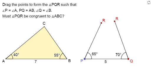
Exploring the Conditions for Congruence of 2 Triangles
This example demonstrates how to construct conic sections (such as ellipses or hyperbolas) within a rectangular frame using dynamic points, and then investigate optimization problems related to area or perimeter percentages. Core mathematical concepts include conic sections, rectangles and polygons, percentage calculations, and optimization. The construction uses GeoGebra commands such as Point, Vector, Sequence, Intersect, Segment, DynamicCoordinates, Polygon, If, and Angle, creating objects like C2, A, B, v, UPoints, C1, u, VPoints, D, E, F, k, j, uCopy, C, f, g, vCopy, C', h, G, d, t1, closed1, text1, i, t3, l, m, n, α, β, γ, δ. Dynamic coordinates and sequences generate point sets, intersections and segments build closed shapes, and angles with conditional logic control variations. Suitable for high school or early college students exploring conic sections and geometric optimization, and useful for dynamic geometry teaching or mathematical modeling.
GeoGebra Commands & Parameters
Point(Sequence[A + (i, 0), i, 1, 20, 1]) → BVector(B, C2) → vSequence((x(B) + (Length[v] * cos(t°)), y(B) + (Length[v] * sin(t°))), t, 0, 355, 5) → UPointsVector(A, C1) → uSequence((x(A) + (Length[u] * cos(t°)), y(A) + (Length[u] * sin(t°))), t, 0, 355, 5) → VPointsIntersect(Ray[D, Rotate[D + (1, 0), 40°, D]], Ray[E, Rotate[E - (1, 0), (-(55°)), E]]) → FSegment(F, D) → kSegment(E, F) → jDynamicCoordinates(C1, x(ClosestPoint[VPoints, C1]), y(ClosestPoint[VPoints, C1])) → CSegment(A, C) → fSegment(A, B) → gDynamicCoordinates(C2, x(ClosestPoint[UPoints, C2]), y(ClosestPoint[UPoints, C2])) → C'Segment(C', B) → hIntersect(Ray[A, C], Ray[B, C']) → GPolygon({A, B, G}) → t1If(C ≟ G ∧ C' ≟ G, true, false) → closed1Segment(D, E) → iPolygon(D, E, F) → t3, l, m, nAngle(E, D, F) → αAngle(B, A, C) → βAngle(F, E, D) → γAngle(C', B, A) → δ
AI Drawing Prompt Reference
Create a plane construction that starts from a horizontal baseline by generating a sequence of discrete points, then select a couple of reference points that define two direction vectors. From each reference point, draw rays at prescribed rotations and compute their intersection to obtain a key vertex, then draw segments linking that vertex to the corresponding endpoints. Build two variable center points by projecting/locating them as closest points onto the generated point sets along the two directions, and connect these centers to the appropriate endpoints. Intersect rays from the baseline endpoints through the variable centers to determine a third vertex, then connect the three main vertices to form a triangle; keep it displayed only when the relevant vertex coincidences match a closure condition. Finally, draw the additional triangle edges using the three intersection/reference points and add angle markings at the prescribed triple-point locations so the angles update as the construction moves.
The prompt above was compiled from the original drawing commands and is for reference only.