
Geometric Transformations of a Dome
Loading the math board and drawing, please wait…
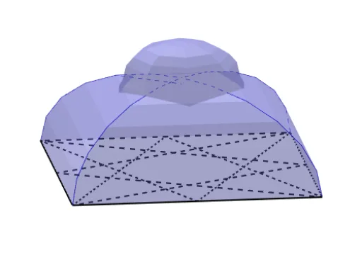
This example demonstrates the geometric transformations and centroid calculation of a dome structure. It involves core concepts like centroid, geometric transformations (rotation, reflection), and polygon construction. GeoGebra commands and objects used include segment, intersect, plane, circle arc, point, line, rotate, mirror, midpoint, polygon, sequence, and distance. Suitable for high school and above students learning solid geometry, transformations, and centroid computation.
GeoGebra Commands & Parameters
Segment(C, D) → hSegment(B, C) → gIntersect(g, yAxis) → GPlane(B, D, H_1) → diagCircleArc(G, C, I) → cPoint(c) → KLine(J_1, h) → sRotate(J_1, 90°, zAxis) → PPoint(c) → JLine(I_1, h) → tRotate(I_1, 90°, zAxis) → S_1Segment(D, A) → iLine(S_1, i) → g_1Intersect(g_1, t) → TMirror(T, vgl1) → T'Line(P, i) → f_1Intersect(f_1, s) → UMirror(U, vgl1) → U'Segment(T', U') → i_2Segment(A, B) → fIntersect(f, xAxis) → FPlane(D, F, F + (0, 0, 1)) → snijIntersect(i_2, snij) → D_2Segment(N_3, D_2) → h_6Mirror(D_2, zAxis) → K_2Midpoint(D_2, K_2) → L_2CircleArc(L_2, K_2, M_2) → d_3Point(d_3) → Q_2Mirror(V_2, diag) → B_3Segment(N_3, M_3) → c_5Point(d_3) → P_2Mirror(U_2, diag) → A_3Segment(M_3, L_3) → d_5Point(d_3) → O_2Mirror(T_2, diag) → Z_2Segment(L_3, K_3) → e_5Point(d_3) → N_2Mirror(S_2, diag) → W_2Segment(J_3, E_3) → g_6Segment(K_3, J_3) → f_6Intersect(i, yAxis) → EPoint(xAxis) → HCircleArc(G, I, B) → dPoint(c) → LPoint(c) → MPoint(c) → NLine(J, g) → jLine(K, g) → kLine(L, g) → lLine(M, g) → mLine(N, g) → nMirror(I_1, vgl1) → N_1Mirror(J_1, vgl1) → O_1Mirror(K_1, vgl1) → P_1Mirror(L_1, vgl1) → Q_1Mirror(M_1, vgl1) → R_1Rotate(L_1, 90°, zAxis) → QRotate(M_1, 90°, zAxis) → RRotate(I_1, (-(90°)), zAxis) → SLine(M_1, h) → pLine(L_1, h) → qLine(K_1, h) → rLine(H_1, h) → aLine(R, i) → bLine(Q, i) → eIntersect(r, e) → VIntersect(p, b) → WRotate(K_1, 90°, zAxis) → ZLine(Z, i) → h_1Intersect(r, h_1) → A_1Intersect(q, e) → T_1Mirror(A_1, vgl1) → U_1Mirror(T_1, vgl1) → V_1Mirror(W, vgl1) → W'Polygon(D, A, W', W) → vierhoek1, d_1, a_1, w', wPolygon(W, W', V_1, T_1) → vierhoek2, w_1, i_1, v_1, t_1Polygon(T_1, V_1, U_1, A_1) → vierhoek3, j_1, k_1, u_1, l_1Polygon(A_1, U_1, U', U) → vierhoek4, m_1, n_1, u', uPolygon(U, U', T', T) → vierhoek5, u_2, p_1, t', t_2Polygon(T, T', H_1) → driehoek1, q_1, t_3, r_1Segment(H_1, T) → s_1Segment(T, U) → b_1Segment(U, A_1) → c_1Segment(A_1, T_1) → e_1Segment(T_1, W) → f_2Segment(W, D) → g_2Segment(H_1, T') → h_2Segment(U', U_1) → j_2Segment(U_1, V_1) → k_2Segment(V_1, W') → l_2Segment(W', A) → m_2Sequence(Rotate[vierhoek1, (nn * 90°), zAxis], nn, 1, 4) → l1Sequence(Rotate[vierhoek2, (nn * 90°), zAxis], nn, 1, 4) → l2Sequence(Rotate[vierhoek3, (nn * 90°), zAxis], nn, 1, 4) → l3Sequence(Rotate[vierhoek4, (nn * 90°), zAxis], nn, 1, 4) → l4Sequence(Rotate[vierhoek5, (nn * 90°), zAxis], nn, 1, 4) → l5Sequence(Rotate[driehoek1, (nn * 90°), zAxis], nn, 1, 4) → l6Sequence(Segment[Rotate[H_1, (nn * 90°), zAxis], Rotate[T', (nn * 90°), zAxis]], nn, 1, 2) → l7Sequence(Segment[Rotate[T', (nn * 90°), zAxis], Rotate[U', (nn * 90°), zAxis]], nn, 1, 2) → l8Sequence(Segment[Rotate[U', (nn * 90°), zAxis], Rotate[U_1, (nn * 90°), zAxis]], nn, 1, 2) → l9Sequence(Segment[Rotate[U_1, (nn * 90°), zAxis], Rotate[V_1, (nn * 90°), zAxis]], nn, 1, 2) → l10Sequence(Segment[Rotate[V_1, (nn * 90°), zAxis], Rotate[W', (nn * 90°), zAxis]], nn, 1, 2) → l11Sequence(Segment[Rotate[W', (nn * 90°), zAxis], Rotate[A, (nn * 90°), zAxis]], nn, 1, 2) → l12Midpoint(H, E) → W_1Line(W_1, zAxis) → n_2Distance(W_1, E) → horstraalRotate(vierhoek1, 90°, zAxis) → vierhoek1'Rotate(vierhoek2, 90°, zAxis) → vierhoek2'Rotate(vierhoek3, 90°, zAxis) → vierhoek3'Rotate(vierhoek4, 90°, zAxis) → vierhoek4'Rotate(vierhoek5, 90°, zAxis) → vierhoek5'Intersect(u_2, snij) → Z_1Intersect(m_1, snij) → A_2Intersect(j_1, snij) → B_2Intersect(w_1, snij) → C_2Intersect(snij, vierhoek4') → E_2, F_2Intersect(snij, vierhoek2') → G_2, H_2Segment(D, C_2) → p_2Segment(C_2, B_2) → q_2Segment(B_2, A_2) → r_2Segment(A_2, Z_1) → s_2Segment(Z_1, D_2) → a_2Segment(D_2, F_2) → b_2Segment(F_2, E_2) → c_2Segment(E_2, H_2) → d_2Segment(H_2, G_2) → e_2Segment(G_2, F) → f_3Mirror(l13, diag) → l13'Sequence(Rotate[l13, (nn * 90°), zAxis], nn, 1, 3) → l14Sequence(Rotate[l13', (nn * 90°), zAxis], nn, 1, 3) → l15Segment(B, E) → g_3Segment(B, H) → h_3Segment(C, F) → i_3Segment(C, E) → j_3Segment(D, F) → k_3Segment(D, G) → l_3Segment(A, G) → m_3Segment(A, H) → n_3Rotate(D_2, (-(90°)), zAxis) → I_2Point(l15) → J_2Polygon(Z_1, J_2, D_2) → driehoek2, p_3, z_1, q_3Polygon(J_2, U', D_2) → driehoek3, r_3, s_3, a_3Plane(D_2, U', D_2 + (0, 0, 1)) → spiegMirror(driehoek2, spieg) → driehoek2'Mirror(driehoek3, spieg) → driehoek3'Sequence(Rotate[driehoek2, (nn * 90°), zAxis], nn, 1, 3) → l16Sequence(Rotate[driehoek3, (nn * 90°), zAxis], nn, 1, 3) → l17Sequence(Rotate[driehoek3', (nn * 90°), zAxis], nn, 1, 3) → l18Sequence(Rotate[driehoek2', (nn * 90°), zAxis], nn, 1, 3) → l19Segment(T, H_1) → b_3Segment(L_2, U) → c_3Point(s_2) → D_3Polygon(D_3, D_2, C_3) → driehoek4, e_3, f_4, g_4Sequence(Rotate[driehoek4, (nn * 90°), zAxis], nn, 1, 3) → l20Mirror(driehoek4, spieg) → driehoek4'Sequence(Rotate[driehoek4', (nn * 90°), zAxis], nn, 1, 3) → l21Polygon(C_3, D_2, N_3, O_3) → vierhoek6, h_4, i_4, j_4, o_3Rotate(J_3, (-(45°)), zAxis) → P_3Rotate(K_3, (-(45°)), zAxis) → Q_3Rotate(L_3, (-(45°)), zAxis) → R_3Rotate(M_3, (-(45°)), zAxis) → S_3Rotate(N_3, (-(45°)), zAxis) → T_3Polygon(P_3, J_3, E_3) → driehoek5, k_4, l_4, m_4Polygon(P_3, Q_3, K_3, J_3) → vierhoek7, n_4, p_4, q_4, r_4Polygon(Q_3, R_3, L_3, K_3) → vierhoek8, s_4, t_4, a_4, b_4Polygon(S_3, M_3, L_3, R_3) → vierhoek9, c_4, d_4, e_4, f_5Point(o_3) → U_3Polygon(S_3, U_3, N_3, M_3) → vierhoek10, g_5, u_3, h_5, i_5Polygon(S_3, T_3, M_3) → driehoek6, j_5, k_5, l_5Polygon(T_3, N_3, M_3) → driehoek7, m_5, n_5, p_5Polygon(T_3, C_3, N_3) → driehoek8, q_5, r_5, s_5Polygon(C_3, N_3, D_2) → driehoek9, t_5, a_5, b_5Sequence(Rotate[l22, (nn * 90°), zAxis], nn, 1, 3) → l23Mirror(l22, spieg) → l22'Sequence(Rotate[l22', (nn * 90°), zAxis], nn, 1, 3) → l24Sequence(Rotate[l25, (nn * 90°), zAxis], nn, 1, 3) → l26Segment(D_3, C_3) → i_6Segment(D_3, T_3) → j_6Segment(T_3, S_3) → k_6Segment(S_3, R_3) → l_6Segment(R_3, Q_3) → m_6Segment(Q_3, P_3) → n_6Segment(P_3, E_3) → p_6Sequence(Rotate[l27, (nn * 90°), zAxis], nn, 1, 3) → l28Segment(W', A) → q_6Segment(C_3, D_2) → r_6Segment(C_3, I_2) → s_6Sequence(Segment[Rotate[C_3, (nn * 90°), zAxis], Rotate[D_2, (nn * 90°), zAxis]], nn, 1, 3) → l29Sequence(Segment[Rotate[C_3, (nn * 90°), zAxis], Rotate[I_2, (nn * 90°), zAxis]], nn, 1, 3) → l30
AI Drawing Prompt Reference
Draw a geometric transformation and centroid calculation example of a dome structure. Start by constructing a polygon, then use rotation and reflection to create symmetrical shapes, and calculate the centroid. Show the process of geometric transformations like rotation and reflection, and the construction of polygons along with the centroid's position.
The prompt above was compiled from the original drawing commands and is for reference only.