
Geometric Construction of Kemal Ataturk Portrait
Loading the math board and drawing, please wait…
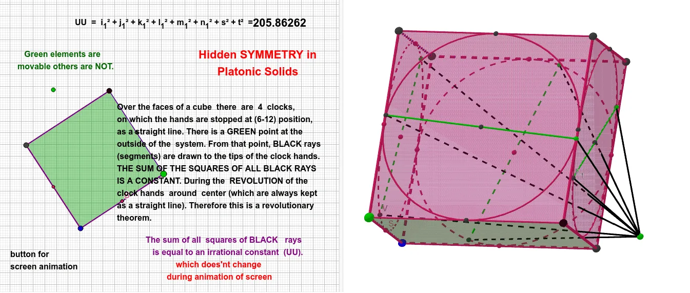
This GeoGebra example constructs a geometric composition themed around Kemal Ataturk, primarily demonstrating the integrated construction and transformation of a 3D cube with 2D polygons, circles, and line segments. Core mathematical concepts include faces and edges of a cube, centroid (barycenter), midpoint, circumcircle, general quadrilaterals, symmetry, and geometric transformations such as translation and rotation. The construction uses commands like Point, Cube, Polygon, Centroid, Midpoint, Circle, Intersect, Line, Segment, and PointIn, creating six faces of the cube (e.g., faceABCD, faceADHE) and twelve edges (e.g., edgeAD, edgeAB), while auxiliary points (J, K, L) are derived from intersections, midpoints, and centroids, resulting in a symmetric geometric pattern. This example is suitable for middle school to early university geometry education, helping students understand the connection between solid and plane geometry, applications of geometric transformations, and how to build complex geometric models through procedural construction.
GeoGebra Commands & Parameters
Point(Circle[B, Distance[A, B], Segment[A, B]]) → CCube(A, B, C) → a, D, faceCDHG, faceEFGH, edgeAD, edgeAB, edgeBC, edgeCD, edgeAE, edgeDH, edgeEH, edgeEF, E, edgeBF, edgeFG, edgeCG, edgeGH, F, G, H, faceABCD, faceADHE, faceABFE, faceBCGFPolygon(E, F, B, A) → q1, e, f_1, b, a_1Polygon(H, E, A, D) → q2, h, e_1, a_2, dCentroid(q1) → JCentroid(q2) → KMidpoint(E, A) → LMidpoint(E, F) → MMidpoint(F, B) → NCircle(L, M, N) → cMidpoint(D, A) → OMidpoint(H, D) → PMidpoint(H, E) → QCircle(P, Q, L) → kIntersect(b, c) → R, SPoint(k) → ILine(I, K) → gIntersect(g, k, 1) → TSegment(I, T) → jPoint(c) → ULine(U, J) → fIntersect(f, c, 1) → VSegment(U, V) → lPointIn(q2) → Pointq2_1PointIn(q2) → Pointq2_2PointIn(q2) → Pointq2_3PointIn(q2) → Pointq2Polygon(G, H, D, C) → q3, g_1, h_1, d_1, c_1Polygon(F, G, C, B) → q4, f_2, g_2, c_2, b_1Centroid(q3) → WCentroid(q4) → ZMidpoint(F, G) → A_1Midpoint(B, C) → B_1Circle(A_1, N, B_1) → pMidpoint(G, C) → C_1Midpoint(G, H) → D_1Circle(C_1, D_1, P) → qPoint(q) → E_1Line(E_1, W) → iIntersect(i, q, 1) → F_1Segment(E_1, F_1) → mPoint(p) → G_1Line(G_1, Z) → nIntersect(n, p, 1) → H_1Segment(G_1, H_1) → rSegment(G_1, I_1) → sSegment(H_1, I_1) → tSegment(E_1, I_1) → i_1Segment(F_1, I_1) → j_1Segment(U, I_1) → k_1Segment(V, I_1) → l_1Segment(T, I_1) → m_1Segment(I, I_1) → n_1
AI Drawing Prompt Reference
Draw a cube with six faces (e.g., faceABCD, faceADHE) and twelve edges (e.g., edgeAD, edgeAB), and construct a symmetric geometric pattern. Start by creating points A and B, then create a circle with A and B as the edge, and use points A, B, and C to create the cube. Next, create quadrilaterals EFB and HAE, calculate their centroids J and K, and the midpoint L of edge EF. Create circle c with L, M, and N, and create circle k with midpoints O (of DA) and P (of HD). Calculate the intersection points R, S of circle c and circle k, and another intersection point I of circle k. Create line g through I and K, calculate the intersection point T of g and k, and create line segment IT. Continue creating other key objects, such as line segments UV, EF, GH, and so on, to form a symmetric geometric pattern.
The prompt above was compiled from the original drawing commands and is for reference only.