
Square Antiprism with 8 Vertices — GeoGebra 3D Construction
Loading the math board and drawing, please wait…
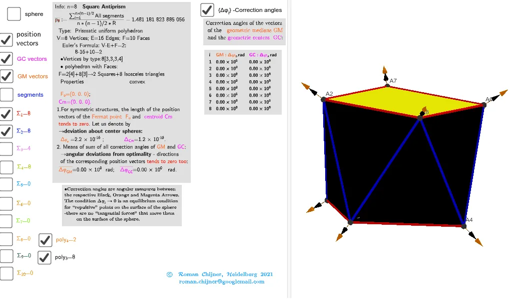
This example demonstrates a 3D square antiprism: two congruent squares are positioned in parallel planes with a relative rotation (or offset), and corresponding vertices are connected to form the characteristic antiprism lateral faces. The key mathematics involves solid geometry of polyhedra, vertex–edge–face relationships, and symmetry/consistent spacing when constructing a structured 8-vertex body. Construction is organized using GeoGebra commands such as Sphere (to define a spherical/3D spatial reference or constraint for vertex placement), Points00 and Segments (to create the vertices and draw the polyhedron edges), Sum and Zip (to combine/pack vertex sets and systematically process the connections), and TableText/Text together with UnicodeToLetter (to label vertices/parameters clearly in the interface). The result is an interactive, labeled visualization suitable for teaching geometric construction, spatial reasoning, and polyhedral structure from high school through undergraduate geometry/pre-modeling practice.
GeoGebra Commands & Parameters
UnicodeToLetter(34) → u34Text("" + Um1) → txt_pSum(Flatten[Sequence[Append[Sequence[Element[txt_p, i], i, m01(k), m02(k)], " "], k, 1, 5]]) → txtUm1Zip(Vector[a, a + UnitVector[a]], a, Points00) → lVector1Zip(Vector[a, a + (1.5 * UnitVector[b])], a, Points00, b, Wi_Pc) → lVector2Zip(Vector[a, a + (1.5 * UnitVector[b])], a, Points00, b, Wi_P) → lVector3Sphere((0, 0, 0), 5) → sphTableText(Append["i", 1…n], Append[" \fgcolor{orange}{GM :Δφ_i}, rad", l1w], Append["\fgcolor{magenta}{GC :Δφ_i} , rad", l1cw], "v") → text23rZip(Segment[Element[Points00, y(a)], Element[Points00, z(a)]], a, ll1bb(1)) → ll1Zip(Segment[Element[Points00, y(a)], Element[Points00, z(a)]], a, ll1bb(2)) → ll2Zip(Segment[Element[Points00, y(a)], Element[Points00, z(a)]], a, ll1bb(3)) → ll3Zip(Segment[Element[Points00, y(a)], Element[Points00, z(a)]], a, ll1bb(4)) → ll4
AI Drawing Prompt Reference
Create a 3D square antiprism. Place two congruent square vertex sets on parallel planes with a relative rotation or offset between them, then connect corresponding vertices pairwise so the characteristic antiprism lateral faces are formed. Use a structured set of 8 vertices to represent the vertex–edge–face relationships, keeping the spacing and edge connections consistent with the two squares. Define the configuration within a 3D reference sphere centered at the origin, and add clear labels for the vertices and key parameters.
The prompt above was compiled from the original drawing commands and is for reference only.