
Geometric Construction of a Parabola Using Focus–Directrix Ideas
Loading the math board and drawing, please wait…
In collections
COORDINATE GEOMETRY
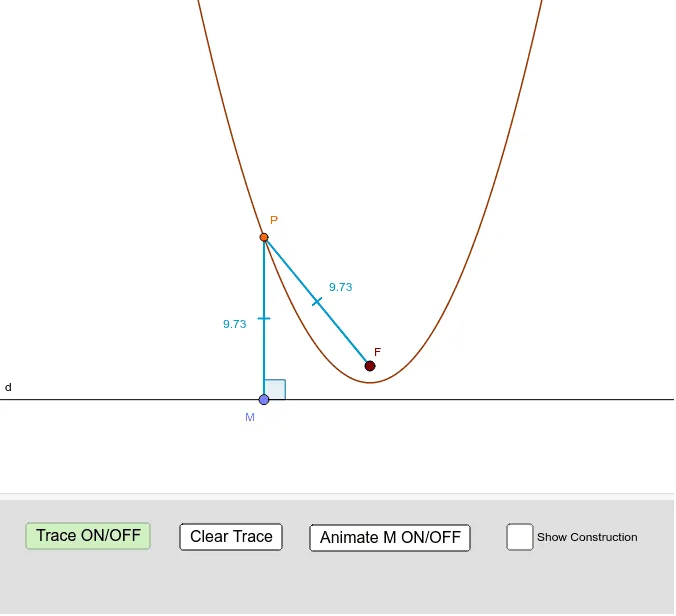
This example demonstrates how to construct a parabola via classic focus–directrix geometry: it sets up the key auxiliary lines and points, then uses a locus process to generate the parabola as the set of points equidistant from the focus and a directrix. The core concepts include the formal definition of a parabola, the role of the focus and directrix, and distance/equidistance constraints realized through standard constructions like angle bisectors and perpendiculars. Construction highlights in GeoGebra come from using Line/Segment/Point to build the baseline geometry, LineBisector to create the needed angular relationship, OrthogonalLine to enforce right-angle distance projections, and Intersect to determine crucial construction points. Finally, Locus is used to trace the required point set, producing the parabola. Angle is employed to define and check angles (e.g., α, β) that drive the construction. Suitable for high-school geometry and introductory analytic geometry, and for interactive classroom demonstrations or self-study.
GeoGebra Commands & Parameters
Line(A, B) → dPoint(d) → MSegment(F, M) → bLineBisector(b) → cOrthogonalLine(M, d) → d_1Intersect(c, d_1) → PSegment(F, P) → eSegment(P, M) → fLocus(P, M) → loc1Angle(b, c) → αAngle(d, d_1) → β
AI Drawing Prompt Reference
On a plane, draw a baseline line d and choose a point M on it. Given a focus F, draw the segment from F to M. From the geometry around the segment F–M, construct an angle-bisector line c associated with that setup, so that it creates the needed angular relationship. Through M, drop a perpendicular line d₁ to the baseline d, then take the intersection point P of c and d₁. Draw the segments from F to P and from P to M. Then trace the locus of the point P as its position is constrained by the distance/equidistance condition between the focus F and the directrix d, producing the parabola. Mark two angles, α from the key angle between the guiding lines, and β as the angle involving the perpendicular direction, for visual checking.
The prompt above was compiled from the original drawing commands and is for reference only.