
Geometric Construction and Transformation of the TEKA Logo
Loading the math board and drawing, please wait…
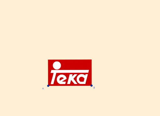
This example demonstrates how to construct a complex logo named 'TEKA' using GeoGebra's geometric construction and transformation tools, starting from basic elements. The core mathematical concepts include two-dimensional vectors, circles and circular arcs, polygons, line segments, mirror reflection, geometric transformations, as well as the visualization of abstract concepts such as expected value and logarithm within the graphic. The construction highlights the use of commands like Line, OrthogonalLine, Vector, OrthogonalVector, LineBisector, Mirror, Intersect, Midpoint, Segment, CircumcircleArc, Polygon, Semicircle, and CircleArc, creating numerous objects (e_2, e_1, B, A, s, b, u, v, F, f, E_1, s_1, A_1, h, f', G, k, H, l, V, f_1, G_1, t_1, f_2, D, i, L, M, I, n, K, F_2, t, n_3, g, m, E, N_1, C_2, D_2) that are combined through precise geometric relationships. It is suitable for high school and above students or teachers to explore the integrated application of geometric transformations, vector operations, and figure construction, and can also serve as a reference for mathematical art design.
GeoGebra Commands & Parameters
Line(A, B) → sOrthogonalLine(A, s) → bVector(A, B) → uOrthogonalVector(u) → vOrthogonalLine(F, b) → fLine(E_1, f) → s_1LineBisector(A_1, A) → hMirror(f, h) → f'Line(G, f') → kLine(H, k) → lOrthogonalLine(V, b) → f_1Line(G_1, f_1) → t_1LineBisector(G_1, V) → f_2OrthogonalLine(D, s) → iIntersect(i, l) → LIntersect(i, f) → ILine(M, I) → nLine(K, n) → tLine(F_2, t) → n_3OrthogonalLine(B, u, xOyPlane) → gLineBisector(A, B) → mIntersect(m, f) → EMirror(i, m) → i'Intersect(i', k) → NLine(N, n) → pLine(C_2, p) → m_3Intersect(m_3, s_1) → H_2Intersect(p, f) → PLine(W, p) → g_1Intersect(f_2, g_1) → I_1Intersect(s_1, g_1) → J_1Midpoint(J_1, I_1) → K_1OrthogonalLine(K_1, g, xOyPlane) → k_2Intersect(n_3, k_2) → G_2Intersect(k_2, m_3) → E_2Segment(I_2, E_2) → p_3CircumcircleArc(D_2, G_2, E_2) → c_3Intersect(t_1, c_3) → J_2, K_2Line(J_2, p_3) → q_3Intersect(q_3, c_3) → L_2, M_2Midpoint(M_2, J_2) → N_2Vector(J_2, N_2) → u_2OrthogonalLine(A_2, g, xOyPlane) → l_3Line(E, t) → r_2Intersect(r_2, l_3) → B_2Intersect(k_2, r_2) → W_1Intersect(i, f') → JOrthogonalLine(A_1, b) → rIntersect(g, r) → CMirror(J, m) → J'Mirror(J, h) → J'_1Mirror(J', h) → J''Polygon(A, B, C, A_1) → q1, a_1, b_1, c, jIntersect(p, l) → OLine(L, n) → qIntersect(q, k) → QPolygon(Q, L, O, N) → q2, q_1, l_1, o, n_1Intersect(t, l) → RPolygon(K, I, M, R) → q3, k_1, i_1, m_1, r_1Intersect(t, k) → SOrthogonalLine(T, k) → dIntersect(d, f') → USemicircle(T, U) → eMirror(e, d) → e'Intersect(f_1, g_1) → ZIntersect(f_1, p) → B_1Polygon(Z, B_1, P, W) → q4, z_1, h_1, p_1, wLine(C_1, g_1) → j_1Intersect(j_1, f_1) → D_1Semicircle(C_1, D_1) → c_1Intersect(j_1, s_1) → F_1Intersect(t_1, j_1) → H_1Semicircle(F_1, H_1) → d_1Polygon(W, C_1, F_1, J_1) → q5, w_1, g_2, h_2, i_2LineBisector(D_1, I_1) → j_2Intersect(k_2, j_2) → L_1CircleArc(L_1, I_1, D_1, xOyPlane) → c_2LineBisector(K_1, H_1) → l_2Intersect(l_2, k_2) → M_1Polygon(D_1, I_1, K_1, H_1) → q6, m_2, n_2, p_2, q_2Line(N_1, r_2) → s_2Intersect(s_2, f_1) → O_1Intersect(r_2, f_1) → P_1OrthogonalLine(R_1, k) → t_2OrthogonalLine(Q_1, l) → a_2Intersect(a_2, f) → S_1Intersect(t_2, f) → T_1Intersect(t_1, r_2) → U_1Mirror(B_2, W_1) → Z_1Polygon(O_1, N_1, P_1, E, Z_1, S_1, T_1, V_1, R_1, Q_1, U_1) → poly1, o_1, u_1, k_3, b_2, e_3, f_3, g_3, h_3, v_1, i_3, j_3Mirror(O_2, N_2) → P_2Semicircle(P_2, O_2, xOyPlane) → d_3Polygon(J_2, E_2, I_2, H_2, C_2, D_2, M_2) → poly2, r_3, s_3, t_3, a_3, b_3, f_4, g_4Semicircle(M_2, J_2, xOyPlane) → c_4LineBisector(D_2, M_2, xOyPlane) → h_4Intersect(h_4, k_2) → Q_2CircleArc(Q_2, M_2, D_2, xOyPlane) → d_4Intersect(l_2, s_1) → R_2CircleArc(R_2, K_1, H_1) → d_2Segment(U, T) → i_4
AI Drawing Prompt Reference
Start with two base points and draw a line through them, then construct a perpendicular line through one point. Use the vector between the points to create an orthogonal vectorholine, and draw parallel lines through other points. Apply angle bisectors and mirror reflections to generate multiple auxiliary lines and intersection points, building a complex geometric framework. Add circles, arcs, polygons, and segments, connecting elements via midpoints, intersections, and perpendiculars, resulting in a symmetric, layered logo with nested shapes and precise crossings.
The prompt above was compiled from the original drawing commands and is for reference only.