
Extremely High Powers: Geometric Construction via Rotation and Polygon Chains
Loading the math board and drawing, please wait…
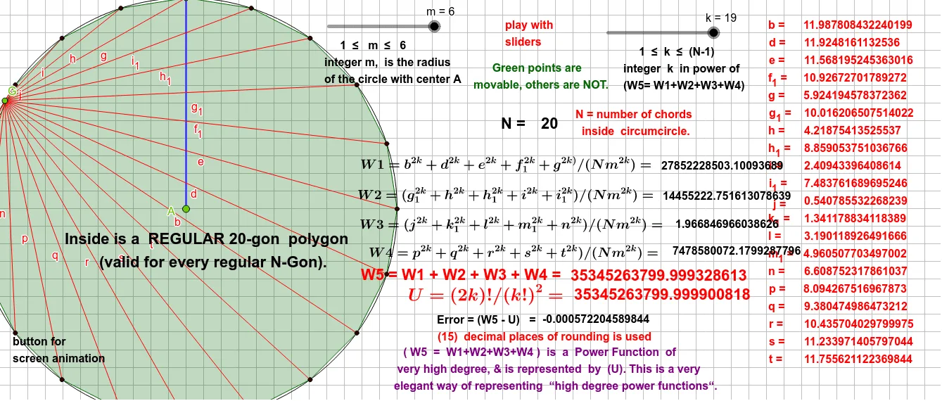
This example demonstrates how repeated rotations and polygon constructions can visually represent the explosive growth of extremely high powers. The core mathematical concepts include power functions, exponential functions, geometric series, and rotational transformations. The construction uses GeoGebra commands such as Circle, Point, Segment, Rotate, Angle, and Polygon to generate points A, B, C, D, E, F and their rotated images (e.g., B', B'', B''', etc.), with angle parameters α, β, γ controlling each rotation step. This creates a spiral chain of polygon edges whose lengths or areas grow polynomially or exponentially with iteration count. It is suitable for high school or early college students to intuitively grasp exponential growth, geometric series, and rotational symmetry in dynamic geometry, and serves as a visual aid for exploring the numerical explosion of very high powers.
GeoGebra Commands & Parameters
Circle(A, m) → cPoint(c) → BSegment(A, B) → fRotate(B, 18°, A) → B'Angle(B, A, B') → αRotate(B', 18°, A) → B''Angle(B', A, B'') → βRotate(B'', 18°, A) → B'''Angle(B'', A, B''') → γRotate(B''', 18°, A) → CAngle(B''', A, C) → δRotate(C, 18°, A) → C'Angle(C, A, C') → εRotate(C', 18°, A) → C''Angle(C', A, C'') → ζRotate(C'', 18°, A) → C'''Angle(C'', A, C''') → ηRotate(C''', 18°, A) → DAngle(C''', A, D) → θRotate(D, 18°, A) → D'Angle(D, A, D') → ιRotate(D', 18°, A) → D''Angle(D', A, D'') → κRotate(D'', 18°, A) → D'''Angle(D'', A, D''') → λRotate(D''', 18°, A) → EAngle(D''', A, E) → μRotate(E, 18°, A) → E'Angle(E, A, E') → νRotate(E', 18°, A) → E''Angle(E', A, E'') → ξRotate(E'', 18°, A) → E'''Angle(E'', A, E''') → οRotate(E''', 18°, A) → FAngle(E''', A, F) → ρRotate(F, 18°, A) → F'Angle(F, A, F') → σRotate(F', 18°, A) → F''Angle(F', A, F'') → τRotate(F'', 18°, A) → F'''Angle(F'', A, F''') → υPoint(c) → GSegment(G, B) → gSegment(G, B') → hSegment(G, B'') → iSegment(G, B''') → jSegment(G, C) → k_1Segment(G, C') → lSegment(G, C'') → m_1Segment(G, C''') → nSegment(G, D) → pSegment(G, D') → qSegment(G, D'') → rSegment(G, D''') → sSegment(G, E) → tSegment(G, E') → bSegment(G, E'') → dSegment(G, E''') → eSegment(G, F) → f_1Segment(G, F') → g_1Segment(G, F'') → h_1Segment(G, F''') → i_1Polygon(C'', C', F, E''', E'', E', E, D''', D'', D', D, C''', C, B''', B'', B', B, F''', F'', F') → poly1, c'', f', f_2, e''', e'', e', e_1, d''', d'', d', d_1, c', c''', c_1, b''', b'', b', b_1, f''', f''
AI Drawing Prompt Reference
Draw a point and a circle around it. Take a point on the circle and connect it to the center. Starting from this point, rotate it by 18 degrees around the center, and connect each rotated point back to the center, recording the angle of each rotation. Repeat this process to create a series of rotated points and connecting lines, forming a spiral pattern that illustrates the relationship between rotations and angle parameters, as well as the complex changes in the shape as the number of rotations increases.
The prompt above was compiled from the original drawing commands and is for reference only.