
Cylinder Net Animation by Sudeep Gokarakonda
Loading the math board and drawing, please wait…
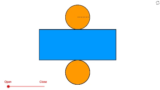
This example demonstrates the unrolling of a cylinder's surface into a 2D net, involving concepts like solid geometry, polygons, circles, and vectors. It uses GeoGebra commands such as Point, Circle, Intersect, Ellipse, Vector, Translate, Polygon, Arc, Segment, Angle, Line, Midpoint, If, Conic, OrthogonalLine, Center, Rotate, Mirror. Ideal for high school students learning about 3D shapes and geometric constructions, or for educational purposes.
GeoGebra Commands & Parameters
Point(xAxis) → ACircle(A, r) → cIntersect(c, xAxis) → B, CEllipse(E, D, C) → eIntersect(xAxis, yAxis) → FVector(F, G) → uTranslate(B, Vector[(u * h)]) → B'_1Translate(C, Vector[(u * h)]) → C'_1Translate(A, Vector[(u * h)]) → A'Translate(e, Vector[(u * h)]) → e'_1Polygon(B'_1, B, C, C'_1) → poly1, b', b, c_1, c'Arc(e'_1, C'_1, B'_1) → fArc(e, B, C) → gArc(e, C, B) → kArc(e'_1, C'_1, B'_1) → p_5Arc(e'_1, B'_1, C'_1) → qArc(e, B, C) → sSegment(A', A) → h_6Segment(A', C'_1) → pAngle(A, A', C'_1) → αLine(A, A') → jIntersect(e'_1, j) → H, IIntersect(k, j) → J,Circle(I, r) → tIntersect(t, j, 2) → KCircle(K, I) → d_1Circle(J, r) → e_1Intersect(e_1, j, 1) → LCircle(L, J) → f_1Intersect(f_1, j, 2) → MIntersect(d_1, j, 2) → NIntersect(s, j) → O,Vector(H, N) → vVector(O, M) → wTranslate(H, Vector[(v * n)]) → H'_1Translate(D, Vector[(u * h)]) → D'Translate(E, Vector[(u * h)]) → E'Line(B, B'_1) → lLine(C, C'_1) → mIntersect(d_1, l, 1) → PIntersect(d_1, m, 1) → QVector(B'_1, P) → zVector(C'_1, Q) → u_1Translate(B'_1, Vector[(z * n)]) → B''Translate(C'_1, Vector[(u_1 * n)]) → C''Midpoint(B'_1, A') → RMidpoint(B, A) → SLine(R, S) → a_1Intersect(q, a_1) → T,Intersect(d_1, a_1, 1) → UVector(T, U) → v_1Translate(T, Vector[(v_1 * n)]) → T'Intersect(f_1, l, 1) → VIntersect(f_1, m, 1) → WIntersect(f_1, a_1, 2) → ZIntersect(s, a_1) → A_1,Vector(B, V) → w_1Vector(A_1, Z) → z_1Vector(C, W) → b_1Translate(B, Vector[(w_1 * (n - 1))]) → B'Translate(A_1, Vector[(z_1 * (n - 1))]) → C_1Translate(O, Vector[(w * (n - 1))]) → O'Translate(C, Vector[(b_1 * (n - 1))]) → C'If(n < 1, B'', P) → B_1If(n < 1, T', U) → D_1If(n < 1, H'_1, N) → E_1If(n < 1, C'', Q) → F_1Conic(B_1, D_1, E_1, F_1, I) → g_1Conic(I, B_1, D_1, E_1, F_1) → h_1If(n < 1, B, If[n < 2, B', V]) → G_1If(n < 1, A_1, If[n < 2, C_1, Z]) → H_1If(n < 1, O, If[n < 2, O', M]) → I_1If(n < 1, C, If[n < 2, C', W]) → J_1Conic(G_1, H_1, I_1, J_1, J) → k_1Vector(H, O) → i_1Translate(H, Vector[(i_1 * (n - 2))]) → H'If(n < 2, H, If[n < 3, H', O]) → K_1Segment(H, K_1) → j_1Arc(e, B, C) → q_1Intersect(g, k_1) → M_1, N_1, R_1, S_1Arc(k_1, M_1, N_1) → r_1Arc(k_1, N_1, M_1) → p_1Arc(e, C, B) → s_1OrthogonalLine(I, j) → l_1OrthogonalLine(J, l) → m_1Circle(I, w_2) → t_1Intersect(t_1, l_1, 1) → L_1Intersect(t_1, l_1, 2) → O_1OrthogonalLine(O_1, l_1) → n_1OrthogonalLine(L_1, m_1) → a_2Intersect(m_1, n_1) → P_1Intersect(m_1, a_2) → Q_1Circle(H, r) → c_2Intersect(c_2, j, 2) → T_1Circle(T_1, H) → d_2OrthogonalLine(H, j) → b_2Intersect(d_2, l_1, 1) → U_1OrthogonalLine(T_1, j) → e_2Intersect(d_2, e_2, 1) → V_1Angle(U_1, T_1, V_1) → βCircle(L_1, r) → f_2Intersect(f_2, l_1, 2) → W_1Vector(I, W_1) → u_2Translate(d_2, Vector[(u_2 * (n - 3))]) → g_2Center(g_2) → Z_1Intersect(g_2, b_2) → A_2, B_3Rotate(A_2, w_3, Z_1) → B_2If(n < 3, H, If[n < 4, B_2, L_1]) → C_2Mirror(C_2, j) → D_2Mirror(E_2, j) → F_2Midpoint(I, L_1) → G_2Intersect(m, l_1) → H_2Midpoint(H_2, C'_1) → I_2Vector(H_2, G_2) → v_2OrthogonalLine(C'_1, m) → i_2Polygon(D_2, F_2, E_2, C_2) → poly2, d_3, f_3, e_3, c_3Vector(C'_1, W_1) → z_2Translate(C'_1, Vector[(z_2 * (n - 3))]) → J_2If(n < 3, C'_1, If[n < 4, J_2, W_1]) → K_2Mirror(K_2, j) → L_2Conic(D_2, L_2, I, K_2, C_2) → h_2Arc(h_2, B_2, D_2) → k_2Arc(h_2, B_2, D_2) → p_2Conic(F_2, N_2, J, M_2, E_2) → q_2Intersect(q_2, k_1) → O_2, P_2, Q_2, R_2Center(h_2) → S_2Center(q_2) → T_2OrthogonalLine(T_2, j) → j_2OrthogonalLine(S_2, j) → m_2Intersect(h_2, m_2) → U_2, V_2Intersect(q_2, j_2) → W_2, Z_2Polygon(U_2, D_2, F_2, W_2) → poly3, u_3, d_4, f_4, w_5Polygon(V_2, C_2, E_2, Z_2) → poly4, v_3, c_4, e_4, z_3Intersect(q_2, d_3, 2) → A_3Intersect(q_2, e_3, 2) → C_3Polygon(F_2, A_3, C_3, E_2) → poly5, f_5, a_3, c_5, e_5Arc(q_2, C_3, A_3) → s_2Arc(q_2, E_2, F_2) → t_2Arc(q_2, E_2, F_2) → g_3Segment(A_3, C_3) → l_2Intersect(k_1, l_2) → D_3, E_3Segment(E_3, A_3) → n_2Segment(D_3, C_3) → b_3Segment(F_2, E_2) → h_3Arc(k_1, D_3, E_3) → k_3Segment(E_3, D_3) → i_3Segment(D_2, C_2) → j_3Segment(L_2, K_2) → l_3Arc(q_2, W_2, F_2) → p_3Arc(q_2, E_2, Z_2) → q_3Arc(q_2, E_2, Z_2) → r_3Arc(q_2, W_2, F_2) → s_3Intersect(k_1, d_3) → F_3, J_3Intersect(k_1, e_3) → G_3, K_3Arc(k_1, G_3, F_3) → t_3Arc(k_1, F_3, R_2) → g_4Arc(k_1, O_2, G_3) → h_4Segment(F_2, E_2) → r_2Intersect(k_1, r_2) → H_3, I_3Segment(F_2, I_3) → m_3Segment(E_2, H_3) → n_3Arc(q_2, E_2, F_2) → k_4Arc(k_1, H_3, I_3) → p_4Segment(I_3, H_3) → a_4Segment(F_2, E_2) → b_4Segment(E_2, Z_2) → i_4Segment(D_2, F_2) → j_4Segment(C_2, E_2) → l_4Arc(k_1, N_1, M_1) → q_4Arc(k_1, N_1, M_1) → r_4Midpoint(j_4) → L_3Translate(e, Vector[(u * h)]) → e'Arc(k_1, M_1, N_1) → s_4Arc(k_1, R_2, N_1) → t_4Arc(k_1, R_2, O_2) → d_5Arc(k_1, P_2, Q_2) → g_5Center(h_1) → M_3Segment(M_3, F_1) → aMidpoint(c_1) → N_3Intersect(k_1, f_4) → A_4,Intersect(k_1, e_4) → B_4,Intersect(g_3, k_1) → C_4, D_4, E_4, F_4Polygon(Z_2, C_4, B_4) → poly7, b_6, z_4, c_6Polygon(F_4, A_4, W_2) → poly8, w_7, f_6, a_6Arc(q_2, W_2, F_4) → d_6Arc(q_2, C_4, Z_2) → e_6Arc(q_2, W_2, F_4) → g_6Arc(q_2, C_4, Z_2) → k_6Arc(k_1, G_3, J_3) → r_6Intersect(k_1, b) → G_4, H_4Segment(N_2, H_4) → j_5Segment(M_2, G_4) → l_5Segment(E_3, D_3) → m_5Segment(H_3, I_3) → n_5
AI Drawing Prompt Reference
Draw an animation of a cylinder's lateral surface unrolling into a flat net. Start with a circle as the base, pick two points on it, and construct an ellipse to represent a tilted cross-section. Create a vertical vector from the origin, and translate the base circle, ellipse, and the two points along this vector to form the top face. Connect corresponding points with segments to form a rectangular side, and draw arcs on the top and bottom faces. Add a vertical segment and an angle marker on the side to indicate the unrolling. Then draw several auxiliary circles and lines, use their intersections to define translation vectors, and move some side points along these vectors to simulate the unfolding. Finally, mark midpoints of key segments and connect them with a reference line.
The prompt above was compiled from the original drawing commands and is for reference only.