
Cylinder Cross-Sections
Loading the math board and drawing, please wait…
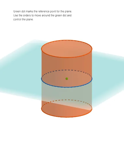
This example demonstrates how the cross-section of a cylinder changes with different slicing planes. Key mathematical concepts include geometric cross-sections, parameterization of cylinders, and spatial transformations. Construction involves GeoGebra commands like Intersect, Cylinder, OrthogonalPlane, and others. Suitable for middle school and above, to help visualize the relationship between solid geometry and function graphs.
GeoGebra Commands & Parameters
Intersect(xAxis, zAxis) → FIntersect(xAxis, zAxis) → APoint(zAxis) → BRay(G, C) → fOrthogonalPlane(G, f) → pCircle(Centering, 4, xOyPlane) → cCylinder(c, 10) → b_{3}, b_{2}, b_{3}IntersectPath(p, b_{3}) → dCorner(d) → H, I, J, K
AI Drawing Prompt Reference
Draw a cylinder with its base centered at the origin, radius 4, and height 10, with its axis along the vertical direction. Inside the cylinder, place an inclined plane that passes through a movable point on the vertical axis and is perpendicular to a ray emanating from that point. Use this plane to slice the cylinder, producing a cross-section curve that is an ellipse or circle depending on the plane's tilt. Mark four vertices on the cross-section and show the intersection line between the plane and the cylinder's lateral surface. Add a slider to control the position of the point on the axis, dynamically changing the shape of the cross-section.
The prompt above was compiled from the original drawing commands and is for reference only.