
Cube Pattern on Sphere Construction
Loading the math board and drawing, please wait…
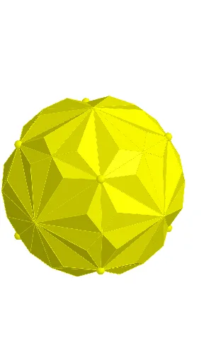
This example demonstrates how to construct and display a cube pattern on a sphere. Using Point, Polygon, and Cube commands to create cube grids, Rotate and Mirror commands for spatial transformations, and Sphere command to generate the spherical surface. Key mathematical concepts include solid geometry, spatial coordinate systems, spherical projection, cube unfolding patterns, and spatial rotation/symmetry transformations. Suitable for high school and university students studying solid geometry, spatial visualization, and GeoGebra software operations.
GeoGebra Commands & Parameters
Point(yAxis) → EPolygon(B, C, D, A) → q1, b, c, d, aCube(q1, true) → e, F, edgeBF, edgeAI, edgeFI, edgeFG, edgeCG, edgeGH, edgeDH, edgeHI, G, H, I, faceABFI, faceBCGF, faceCDHG, faceADHI, faceFGHICentroid(faceCDHG) → JSegment(C, H) → fSegment(D, G) → gMidpoint(C, D) → KMidpoint(C, G) → LMidpoint(G, H) → MMidpoint(H, D) → NSegment(K, M) → hSegment(L, N) → iLine(E, J) → jRotate(C, 22.5°, j) → C'Rotate(H, 22.5°, j) → H'Segment(C', H') → f'Segment(C, D) → kSegment(G, H) → lSegment(K, L) → mIntersect(m, f') → OSegment(C, O) → nSegment(O, J) → pMirror(O, f) → O'Segment(C, O') → qSegment(O', J) → rSegment(O, K) → sSegment(L, O') → tRotate(O', 90°, j) → O''Rotate(J, 90°, j) → J'Segment(O'', J') → r'Rotate(O, 90°, j) → O'_{1}Rotate(J, 90°, j) → J'_{1}Segment(O'_{1}, J'_{1}) → p'Rotate(C, 90°, j) → C'_{1}Rotate(O', 90°, j) → O''_{1}Segment(C'_{1}, O''_{1}) → q'Rotate(C, 90°, j) → C'_{2}Rotate(O, 90°, j) → O'_{2}Segment(C'_{2}, O'_{2}) → n'Rotate(L, 90°, j) → L'Rotate(O', 90°, j) → O''_{2}Segment(L', O''_{2}) → t'Rotate(O, 90°, j) → O'_{3}Rotate(K, 90°, j) → K'Segment(O'_{3}, K') → s'Mirror(O, J'_{1}) → O'_{4}Mirror(O', J'_{1}) → O''_{3}Mirror(O, J'_{1}) → O'_{5}Mirror(J, J'_{1}) → J'_{2}Segment(O'_{5}, J'_{2}) → p'_{1}Mirror(O', J'_{2}) → O''_{4}Mirror(J, J'_{2}) → J'_{3}Segment(O''_{4}, J'_{3}) → r'_{1}Mirror(C, J'_{3}) → C'_{3}Mirror(O', J'_{3}) → O''_{5}Segment(C'_{3}, O''_{5}) → q'_{1}Mirror(C, J'_{3}) → C'_{4}Mirror(O, J'_{3}) → O'_{6}Segment(C'_{4}, O'_{6}) → n'_{1}Mirror(L, J'_{3}) → L'_{1}Mirror(O', J'_{3}) → O''_{6}Segment(L'_{1}, O''_{6}) → t'_{1}Mirror(O, J'_{3}) → O'_{7}Mirror(K, J'_{3}) → K'_{1}Segment(O'_{7}, K'_{1}) → s'_{1}Mirror(O''_{2}, J'_{3}) → PMirror(L', J'_{3}) → L''Mirror(O''_{2}, J'_{3}) → QSegment(L'', Q) → t''Mirror(O'', J'_{3}) → O'''Mirror(J', J'_{3}) → J''Segment(O''', J'') → r''Mirror(C'_{1}, J'') → RMirror(O''_{1}, J'') → SSegment(R, S) → q''Mirror(C'_{2}, J'') → TMirror(O'_{2}, J'') → USegment(T, U) → n''Mirror(O'_{3}, J'') → VMirror(O'_{1}, J'') → WMirror(J'_{1}, J'') → ZSegment(W, Z) → p''Mirror(O'_{3}, Z) → A_1Mirror(K', Z) → K''Segment(A_1, K'') → s''Segment(C'_{2}, C'_{4}) → f_1Segment(C, T) → g_1Ray(E, L') → h_1Ray(E, O) → i_1Ray(E, C) → j_1Ray(E, O') → k_1Ray(E, K'') → l_1Sphere(E, C) → oIntersect(k_1, o) → B_1,Intersect(l_1, o) → C_1,Intersect(i_1, o) → D_1,Intersect(h_1, o) → E_1,Intersect(j, o) → F_1, G_1Polygon(C, G_1, D_1) → t1, d_1, c_1, m_1Polygon(C, B_1, G_1) → t2, n_1, c_2, b_1Polygon(C, D_1, E_1) → t3, e_1, c_3, p_1Polygon(C, C_1, B_1) → t4, q_1, c_4, r_1Intersect(j, p'_{1}) → H_1Polygon(C_1, G_1, B_1) → t5, s_1, t_1, a_1Polygon(G_1, E_1, D_1) → t6, f_2, g_2, h_2Rotate(l1, 90°, j) → l1'Rotate(l1, 180°, j) → l1'_{1}Rotate(l1, 270°, j) → l1'_{2}Rotate(l1, 0°, j) → l1'_{3}Line(E, C) → i_2Rotate(l2, 120°, i_2) → l2'Rotate(l2, (-(120°)), i_2) → l2'_{1}Rotate(l2, 0°, i_2) → l2'_{2}Line(E, B) → j_2Rotate(l2', 120°, j_2) → l2''Rotate(l2'', (-(120°)), i_2) → l2'''Rotate(l2'', 120°, i_2) → l2'''_{1}
AI Drawing Prompt Reference
Construct a cube pattern on a sphere. First, determine points on the sphere. Then, create a cube grid. Next, apply rotation and mirroring commands for spatial transformations. Finally, connect key points and draw line segments to form a symmetric cube pattern.
The prompt above was compiled from the original drawing commands and is for reference only.