
Cube Cross Sections by Aedamar Frawley
Loading the math board and drawing, please wait…
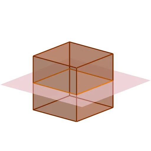
This example demonstrates the variety of cross-section shapes obtained by rotating a cube. It involves core math concepts like solid geometry, geometric transformations, vectors, and polygons. Constructed using commands such as Rotate, Point, Cube, and IntersectPath to create and analyze intersections. Suitable for high school and university-level geometry education, enhancing spatial reasoning and understanding of 3D shapes.
GeoGebra Commands & Parameters
Rotate(Translate[Rotate[Plane[(0, 0, 0), (0, 1, 0), (1, 0, 0)], b, xAxis], Vector[(0, 0, d)]], c, zAxis) → ePoint(Circle[(1, -1, -1), Distance[(-1, -1, -1), (1, -1, -1)], Segment[(-1, -1, -1), (1, -1, -1)]]) → ACube((-1, -1, -1), (1, -1, -1), A) → g, B, faceABFE, faceCDEF, edge2, edge1, edge4, edgeAB, edge3, edgeBF, edgeCF, edgeCD, C, edge5, edgeDE, edgeAE, edgeEF, D, E, F, face1, face3, face2, face4IntersectPath(e, g) → poly1, G, H, I, J, f, h, i, j
AI Drawing Prompt Reference
Draw a 3D cube with its base defined by two opposite vertices and a third point on the perpendicular bisector of the base edge. Rotate the cube around the vertical axis. Create a plane that is first rotated about the horizontal axis, then translated vertically, and finally rotated about the vertical axis. Intersect this plane with the cube to generate a polygonal cross-section inside the cube, formed by connecting the intersection points on the cube's edges. Show how the cross-section shape changes as the plane rotates.
The prompt above was compiled from the original drawing commands and is for reference only.