
Cross Section & Relative Position
Loading the math board and drawing, please wait…
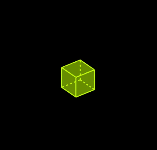
This example demonstrates the dynamic changes in the cross-sectional shapes of 3D geometric solids (like a cube) and their relative positions. It involves core mathematical concepts such as polygons, similar triangles, solid geometry, and geometric construction. The construction utilizes GeoGebra commands/objects like Polygon, Intersect, OrthogonalLine, Point, Plane, CircleArc, Circle, Line, Segment, PointIn, and Cube. It is suitable for high school and above students studying solid geometry, geometric construction, and spatial reasoning, as well as for demonstrating related topics.
GeoGebra Commands & Parameters
Polygon(C, D, B, A) → q1, c, d, b, aIntersect(b, yAxis) → EIntersect(c, yAxis) → FIntersect(xAxis, d) → GIntersect(a, xAxis) → HOrthogonalLine(E, xOyPlane) → fOrthogonalLine(G, xOyPlane) → gOrthogonalLine(F, xOyPlane) → hOrthogonalLine(H, xOyPlane) → iPoint(f) → IPoint(yAxis) → JPlane(E, J, I) → eCircleArc(E, I, J) → k_2Point(k_2) → P_2Plane(A, B, P_2) → jCircle(A, 4, j) → pCircle(B, 4, j) → qLine(P_2, b) → lIntersect(l, p) → L, MIntersect(l, q) → N, OPolygon(A, B, N, P_2, L) → poly1, a_1, b_1, n, k_5, l_1Point(i) → PPoint(xAxis) → QCircleArc(H, Q, P) → k_3Point(k_3) → P_3Plane(C, A, P_3) → mLine(P_3, a) → sCircle(C, 4, m) → tCircle(A, 4, m) → c_1Intersect(s, t) → S, TIntersect(s, c_1) → U, VPolygon(C, A, U, P_3, S) → poly2, c_2, a_2, u, r_1, s_1Point(g) → WPoint(xAxis) → ZCircleArc(G, W, Z) → k_1Point(k_1) → P_1Plane(B, D, P_1) → oLine(P_1, d) → f_1Circle(B, 4, o) → e_1Circle(D, 4, o) → g_1Intersect(f_1, e_1) → B_1, C_1Intersect(f_1, g_1) → D_1, E_1Polygon(B, D, D_1, P_1, B_1) → poly3, b_2, d_2, h_1, i_1, j_1Point(h) → F_1Point(yAxis) → G_1CircleArc(F, F_1, G_1) → k_4Point(k_4) → P_4Plane(D, C, P_4) → kLine(P_4, c) → rCircle(D, 4, k) → d_1Circle(C, 4, k) → p_1Intersect(r, d_1) → K, RIntersect(r, p_1) → A_1, H_1Point(r) → I_1Polygon(D, C, A_1, I_1, K) → poly4, d_3, c_3, m_1, n_1, k_6Point(zAxis) → J_1Point(zAxis) → K_1Segment(J_1, K_1) → q_1PointIn(poly2) → A_2PointIn(poly2) → B_2PointIn(poly2) → C_2PointIn(poly2) → D_2PointIn(poly1) → E_2PointIn(poly1) → F_2PointIn(poly1) → G_2PointIn(poly1) → H_2PointIn(poly3) → I_2PointIn(poly3) → J_2PointIn(poly3) → K_2PointIn(poly3) → L_2Polygon(I_2, J_2, K_2, L_2) → q4, r_2, s_2, t_2, e_2PointIn(poly4) → M_2PointIn(poly4) → N_2PointIn(poly4) → O_2Point(zAxis) → R_2PointIn(poly4) → S_2Polygon(N_2, O_2, S_2, M_2) → q5, f_3, o_2, g_3, h_3Polygon(F_2, G_2, H_2, E_2) → q6, i_3, j_3, l_3, m_3Polygon(B_2, C_2, D_2, A_2) → q7, n_3, p_3, q_3, r_3Point(zAxis) → L_1Plane(L_1, xOyPlane) → wPointIn(w) → R_1PointIn(w) → S_1Point(Circle[S_1, Distance[R_1, S_1], Segment[R_1, S_1]]) → T_1Cube(R_1, S_1, T_1) → u_1, U_1, face5, face6, edge2, edge1, edge4, edge6, edge3, edge8, edge10, edge9, V_1, edge5, edge11, edge7, edge12, W_1, Z_1, T_2, face1, face3, face2, face4PointIn(q1) → U_2PointIn(q1) → V_2PointIn(q1) → W_2PointIn(q1) → Z_2Point(zAxis) → B_3Segment(A_3, B_3) → s_3Point(c_2) → C_3Line(C_3, s_3) → t_3Segment(A_3, C_3) → a_3Point(t_3) → D_3Line(D_3, a_3) → b_3Line(B_3, b_3) → e_3Intersect(t_3, e_3) → E_3Point(t_3) → F_3Line(F_3, b_3) → t_1Point(b_3) → M_1Intersect(t_1, zAxis) → N_1Intersect(b_1, j_1) → O_1Point(b_2) → Q_1Point(d_3) → Q_2OrthogonalLine(O_1, q1) → f_2OrthogonalLine(Q_2, q1) → g_2OrthogonalLine(Q_1, q1) → h_2Intersect(e_3, h_2) → G_3Intersect(t_1, h_2) → H_3Segment(O_1, A_3) → i_2Line(N_1, i_2) → j_2Line(B_3, i_2) → l_2Intersect(f_2, j_2) → I_3Intersect(g_2, j_2) → J_3Intersect(l_2, g_2) → L_3Segment(D_3, F_3) → m_2Segment(C_3, E_3) → n_2Point(m_2) → P_5Point(n_2) → P_6Plane(P_5, xOyPlane) → vPointIn(v) → O_3Polygon(O_3, P_5, 4, xOyPlane) → poly5, p_2, q_2, f_4, g_4, Q_3, R_3Plane(P_6, xOyPlane) → o_1PointIn(o_1) → K_3Polygon(K_3, P_6, 4, xOyPlane) → poly6, h_4, i_4, j_4, l_4, T_3, U_3PointIn(poly5) → N_3PointIn(poly5) → M_3PointIn(poly5) → V_3PointIn(poly5) → W_3Polygon(M_3, N_3, W_3, V_3) → q2, m_4, n_4, w_3, v_3OrthogonalLine(M_3, poly6) → p_4OrthogonalLine(V_3, poly6) → q_4OrthogonalLine(W_3, poly6) → r_4OrthogonalLine(N_3, poly6) → s_4Intersect(q_4, poly6) → Z_3Intersect(p_4, poly6) → A_4Intersect(r_4, poly6) → B_4Intersect(s_4, poly6) → C_4Polygon(A_4, C_4, B_4, Z_3) → q3, a_4, c_4, b_4, z_3Intersect(edge3, edge2) → D_4Intersect(edge10, edge12) → E_4Segment(D_4, E_4) → t_4Intersect(edge4, edge6) → F_4Segment(E_4, F_4) → d_4Point(edge9) → G_4Segment(F_4, G_4) → e_4Point(j_3) → H_4Point(l_3) → I_4Segment(H_4, I_4) → f_5Intersect(i_3, j_3) → J_4Segment(I_4, J_4) → g_5Intersect(m_3, i_3) → K_4Segment(J_4, K_4) → h_5Intersect(r_3, q_3) → L_4Point(p_3) → M_4Segment(L_4, M_4) → i_5Point(p_3) → N_4Intersect(r_3, n_3) → O_4Segment(N_4, O_4) → j_5Segment(N_4, M_4) → l_5Intersect(r_2, s_2) → Q_4PointIn(poly3) → R_4Segment(Q_4, R_4) → m_5Intersect(s_2, t_2) → S_4Point(r_2) → T_4Segment(S_4, T_4) → n_5Segment(R_4, S_4) → p_5Point(v_3) → U_4Point(v_3) → V_4Segment(U_4, V_4) → q_5Intersect(n_4, w_3) → W_4Segment(W_4, V_4) → r_5Intersect(m_4, n_4) → Z_4Segment(W_4, Z_4) → s_5Intersect(a_4, z_3) → A_5Point(z_3) → B_5Intersect(c_4, b_4) → C_5Intersect(a_4, c_4) → D_5Intersect(h_3, g_3) → E_5Point(g_3) → F_5Segment(E_5, F_5) → c_5Intersect(f_3, h_3) → G_5Segment(F_5, G_5) → d_5Intersect(f_3, o_2) → H_5Segment(G_5, H_5) → e_5Point(z_3) → I_5Point(z_3) → J_5Segment(I_5, J_5) → t_5Point(b_4) → K_5Segment(J_5, K_5) → a_5Point(c_4) → L_5Segment(K_5, L_5) → b_5Intersect(edge9, edge3) → M_5Intersect(edge6, edge2) → N_5Segment(M_5, N_5) → f_6Intersect(edge11, edge7) → O_5Segment(N_5, O_5) → g_6Point(edge4) → Q_5Segment(O_5, Q_5) → h_6Intersect(edge5, edge1) → R_5Intersect(f_6, edge3) → S_5Segment(R_5, S_5) → i_6Intersect(f_6, edge2) → T_5Segment(S_5, T_5) → j_6Intersect(h_6, g_6) → U_5Segment(T_5, U_5) → l_6Intersect(edge5, edge11) → V_5Segment(U_5, R_5) → m_6
AI Drawing Prompt Reference
Draw a cube and its three different plane sections. First, draw a cube, then draw section polygons on three different planes. Start by drawing a section polygon on the xOy plane, followed by section polygons on the yOz and xOz planes. Ensure each section polygon intersects with the corresponding face of the cube.
The prompt above was compiled from the original drawing commands and is for reference only.