
Core of Four Connected Cylinders
Loading the math board and drawing, please wait…
In collections
intersection: surface-surface, curve-curve
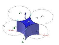
This example demonstrates the central part of four connected cylinders. It involves core mathematical concepts such as parametric curves, solid geometry, and quadratic equations. Using GeoGebra commands like Circle, Point, Join, Polygon, Mirror, Surface, and CurveCartesian, this complex geometric figure can be constructed. Suitable for high school mathematics education and learning.
GeoGebra Commands & Parameters
Circle(M_0, r, xOyPlane) → c_0Point(c_0, 0) → APoint(c_0, 1 / 4) → BJoin({{M}, Sequence[Point[c_0, j], j, 0, 1 / 4 + 0.01, 0.01]}) → l1Polygon(l1) → poly1Mirror(poly1, Line[M, B]) → poly2Mirror(poly1, Line[A, M]) → poly1'Mirror(poly2, Line[A, M]) → poly2'Surface(M_0 + ((r * sin(t)), (r * cos(t)), u - h), t, pi, pi + pi / 2, u, 0, h) → aSurface(C - ((r * sin(t)), (r * cos(t)), 0) + ((r * sin(k)), (r * cos(k)), 0), t, pi, (3 * pi / 2), k, ((-pi)) / 2, 0) → eSurface(M_0 + ((r * sin(t)), (r * cos(t)), 0) + (u * (M - (M_0 + ((r * sin(t)), (r * cos(t)), 0)))), t, pi, (pi * 3 / 2), u, 0, 1) → f''CurveCartesian(M_1 + ((r * cos(t)), (r * sin(t)), 0), t, pi / 2, pi) → r_1Surface(M_1 + ((r * cos(t)), (r * sin(t)), 0) + (u * ((-M_1) - ((r * cos(t)), (r * sin(t)), 0) + M)), t, pi / 2, pi, u, 0, 1) → f'''CurveCartesian(M_0 + ((r * sin(t)), (r * cos(t)), 0), t, pi, (pi * 3 / 2)) → r_0Surface(r_1(t) + (u * (r_0(t + pi / 2) - r_1(t))), t, pi / 2, pi, u, 0, 1) → fMirror(f, Line[A, C]) → f'Mirror(a, Plane[Line[A, C], Line[A, (x(A), y(A), 0)]]) → a'Surface(M_1 + ((r * sin(t)), (r * cos(t)), u - h), t, ((-pi)) / 2, 0, u, 0, z(M_0)) → bMirror(b, Plane[Line[A, C], Line[A, (x(A), y(A), 0)]]) → b''Circle(M_1, r, xOyPlane) → c_1Circle(M_3, r, xOyPlane) → c_3Circle(M_2, r, xOyPlane) → c_2CurveCartesian(M_2 + ((r * cos(t)), (r * sin(t)), 0), t, 0, pi / 2) → r_2CurveCartesian(M_3 + ((r * cos(t)), (r * sin(t)), 0), t, (3 / 2 * pi), (2 * pi)) → r_3
AI Drawing Prompt Reference
Draw a central part of four connected cylinders. The figure includes a circular base, a connecting line, a polygon, and two mirrored polygons. The construction order is to first draw the circle and connecting line, then create the polygon, followed by mirroring to generate mirrored polygons, and finally combining these parts into a complex geometric shape.
The prompt above was compiled from the original drawing commands and is for reference only.