
Cone Surface Area Visualization with Integral Construction
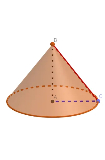
Loading the math board and drawing, please wait…
This example demonstrates how to visualize and conceptually derive the surface area of a cone by slicing it into infinitesimal elements and interpreting the result through integration. It focuses on the key geometry parameters of a cone—base radius r, height h, and slant height—and on the functional relationship between a slice’s radius and its position, typically obtained using similar triangles. The construction then supports the integral-based computation of the cone’s lateral (surface) area. In GeoGebra, it is built using commands Intersect (to create intersection points), Circle (to define circular cross-sections or auxiliary circles), Cone (to construct the 3D cone), Segment (to form defining/connecting line segments such as generatrices), and Point (to place driving points). The model is parameterized by objects such as A, r, h and additional constructed points (c, e, f, g, B, i, C, j, k), with text labels (text1–text6) for guiding the displayed quantities. Suitable for high school advanced geometry and early calculus/analysis lessons, especially for teaching the workflow: geometry similarity → function modeling → integral for area.
GeoGebra Commands & Parameters
Intersect(xAxis, yAxis) → ACircle(A, r) → cCone(c, h) → e, f, gIntersect(zAxis, f, 1) → BSegment(B, A) → iPoint(c) → CSegment(A, C) → jSegment(B, C) → k
AI Drawing Prompt Reference
Create a 3D diagram centered on a cone: set up the key geometry parameters using a base radius and a height. First, draw a reference circle on the horizontal plane by fixing a center point and a radius. Use that circle together with the specified height to construct the cone and obtain the important auxiliary points related to the cone’s geometry. On the vertical axis, place an intersection point connected to one of the cone’s auxiliary points, then draw a segment between this axis point and the planar reference point to indicate distance. Finally, mark the circle’s center point and draw segments from it to the planar reference point and to the axis intersection point, supporting visual understanding of cross-sections and the relationship of radii along the height.
The prompt above was compiled from the original drawing commands and is for reference only.