
Bohemian Dome: Intersection of a Parallelepiped and an Integral Surface
Loading the math board and drawing, please wait…
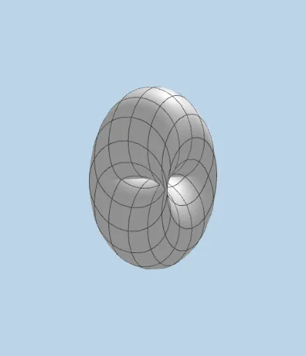
① This example demonstrates a three-dimensional geometric object called the 'Bohemian Dome', formed by intersecting a parallelepiped with a curved surface, with interactive buttons and sliders to explore its construction. ② Core mathematical concepts include intersection of planes and solids, parallelograms as base faces, spatial structure of a parallelepiped, and integral calculus for defining or visualizing surface area or volume. ③ Construction highlights: from the summary, GeoGebra commands such as Polygon (to build the base), IntersectPath (to compute intersection curves between planes and solid surfaces), and Surface (to generate the dome) are used; additional objects include rotations (rotasi, rotano), axes (ejessi, ejesno), buttons (botón) for animation control, color objects (red, green, blue), and text labels (texto1). ④ Suitable for high school to university courses in solid geometry, calculus, or mathematical modeling, providing an intuitive way to understand cross-section methods, integral volume computation, and interactive 3D geometric design.
GeoGebra Commands & Parameters
Polygon(A, B, C, D) → c1, a_1, b_1, c_1, d_1IntersectPath(d, c) → eSurface((a * cos(u)), (b * cos(v)), (a * sin(u)) + (b * sin(v)), u, 0, β, v, 0, (2 * π)) → Domo
AI Drawing Prompt Reference
Draw a 3D Bohemian dome formed by intersecting a parallelepiped with a curved surface. The parallelepiped has a parallelogram base defined by four vertices. The surface is generated using sine and cosine components, creating a wavy dome shape. At the intersection of the parallelepiped and the surface, an intersection curve is shown to reveal their spatial relationship. Include rotatable axes, an animation control button, red, green, and blue color objects, and text labels for interactive exploration. Construction order: first build the base polygon, then generate the surface, then compute the intersection curve, and finally add auxiliary elements.
The prompt above was compiled from the original drawing commands and is for reference only.