
Angle Between a Line Segment and a Plane — Solid Geometry Demo
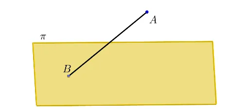
Loading the math board and drawing, please wait…
This GeoGebra example demonstrates how to construct and measure the angle formed between a line segment and a plane in three-dimensional space, a fundamental topic in solid geometry. Core mathematical concepts include: the normal vector of a plane, the orthogonal projection of an oblique line onto the plane, and the right triangle formed by the original segment, its projection, and the perpendicular from the segment's endpoint to the plane—the acute angle between the segment and its projection is precisely the line-plane angle. Construction steps involve: using Polygon to define the reference plane; employing OrthogonalLine to drop a perpendicular from a segment endpoint to the plane, then using Intersect to locate the foot of the perpendicular and the projected segment; drawing the original segment and its projection via Segment; and applying Angle to compute or display the measure of the line-plane angle. Auxiliary tools such as Circle and PointIn may explore loci, while Midpoint assists in verifying geometric properties. This example is suitable for high school mathematics (solid geometry units), undergraduate analytic geometry courses, classroom demonstrations by teachers, and student self-paced exploration.
GeoGebra Commands & Parameters
Polygon(A, B, C, D) → poly1, a, b, c, dOrthogonalLine(E, xOyPlane) → fIntersect(f, poly1) → FSegment(F, E) → lSegment(A, C) → mCircle(A, 1, l) → pIntersect(m, p, 1) → GPointIn(poly1) → HSegment(H, E) → gSegment(H, F) → hMidpoint(H, E) → IMidpoint(E, I) → JMidpoint(I, H) → KOrthogonalLine(J, poly1) → iOrthogonalLine(I, poly1) → jOrthogonalLine(K, poly1) → kIntersect(h, k) → LIntersect(h, j) → MIntersect(h, i) → NAngle(H, L, K) → αAngle(L, M, I) → βAngle(M, N, J) → γAngle(N, F, E) → δSegment(J, N) → nSegment(I, M) → qSegment(K, L) → rAngle(F, H, E) → εMidpoint(E, F) → O
AI Drawing Prompt Reference
Visualize the angle between a line segment and a plane in 3D space. Construct a reference plane using four points, drop a perpendicular from one endpoint of the line segment to the plane to find the foot and the projection. Draw the original segment and its projection, then measure the acute angle between them, which represents the line-plane angle. Include auxiliary elements like perpendicular bisectors and midpoints for further geometric exploration.
The prompt above was compiled from the original drawing commands and is for reference only.