
All/None: Geometry Connections Map
Loading the math board and drawing, please wait…
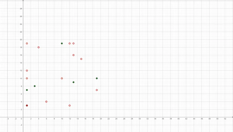
This example demonstrates an “All/None” phenomenon using a Connections Map: from a set of constructed points under specific geometric/functional conditions, certain connections are included while others are excluded, producing a clear full-or-empty relationship structure. It centers on coordinate geometry (points and line segments), congruence-based reasoning (how connections can be judged by equality of geometric measures), and a statistics-oriented viewpoint for organizing and visualizing relationship patterns. The construction uses many point objects (A through S) as a base set, forms line segments to represent the connection graph, and (where applicable) employs linear functions or derived measures to drive the selection rule that determines which connections appear. Suitable for secondary school through early undergraduate learners, and useful for teaching geometric relationship classification, congruence intuition, and visual, data-like representations of structure.
GeoGebra Commands & Parameters
(12, 19)(1, 3)(1, 7)(10, 19)(12, 3)(1, 3)(19, 10)(3, 8)(13, 9)Point J(6, 4)Point K(10, 10)(19, 7)(15, 15)(1, 10)(4, 18)(1, 19)(13, 16)(1, 12)(13, 19)
AI Drawing Prompt Reference
In a Cartesian coordinate plane, plot a set of discrete points, including the points J(6,4) and K(10,10), together with the coordinate points (12,19), (1,3), (1,7), (10,19), (12,3), (1,3), (19,10), (3,8), (13,9), (19,7), (15,15), (1,10), (4,18), (1,19), (13,16), (1,12), and (13,19). Then draw a “connections map” style relationship graph by adding line segments only for specific selected pairs, leaving other pairs unconnected, to create a clear all-or-none full/empty connection pattern. Place and label the points first, then apply a condition-based selection rule to decide which connections appear, and render the resulting network of segments.
The prompt above was compiled from the original drawing commands and is for reference only.