
棱柱截面绘制
几何画板及绘图内容加载中,请稍等……
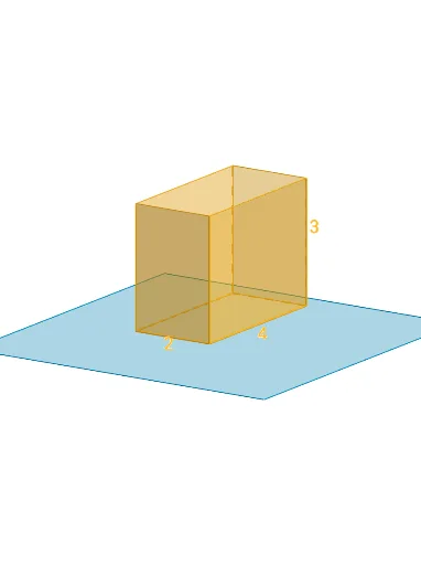
①本范例演示如何通过动态交互绘制棱柱的截面图形;②涉及的核心数学概念包括棱柱结构、截面几何、几何变换(平移、旋转)、解析几何;③作图要点提炼自构造摘要,使用了Polygon(多边形)、PointIn(点在路径上)、Translate(平移)、Rotate(旋转)、Prism(棱柱)、Plane(平面)、IntersectPath(路径相交)、OrthogonalLine(垂线);④适合高中立体几何教学,用于理解截面与原几何体的关系,培养空间想象能力。
GeoGebra 命令及参数
Polygon(B + (-2, -2), B + (2, -2), B + (2, 2), B + (-2, 2)) → poly3, e, f, g, iPointIn(poly3) → CTranslate((0, 0, 0), Vector[B, C]) → APolygon(A + (-4, -4), A + (4, -4), A + (4, 4), A + (-4, 4)) → poly1, a, b, c, dRotate(Rotate[Translate[poly1, Vector[A, A + (0, 0, h)]], (90° * s), A + (0, 0, h), yAxis], (90° * t), A, zAxis) → poly2Prism(Polygon[(1, 2, 0), (1, -2, 0), (-1, -2, 0), (-1, 2, 0)], 3) → m, M, edge1, edge2, edge3, edge4, edge5, edge6, edge7, edge8, N, Q, R, face1, face2, face3, face4, face5Rotate(D, 120°, (0, 0, 0)) → EPolygon(D, E, 3, xOyPlane) → poly4, j, k, l, FPointIn(poly2) → GPointIn(poly2) → HPointIn(poly2) → IPlane(G, I, H) → nIntersectPath(n, m) → poly6, poly5, r, a_1, b_1, c_1, K, L_1, O, P, J, L, p, qRotate(m, 0, zAxis) → m'Rotate(m, 0, zAxis) → m'_1OrthogonalLine(A, n) → d_1