
Vectors and Bearings (Copy)
Loading the math board and drawing, please wait…
In collections
MTH-5173-2-St. Lawrence Seaway
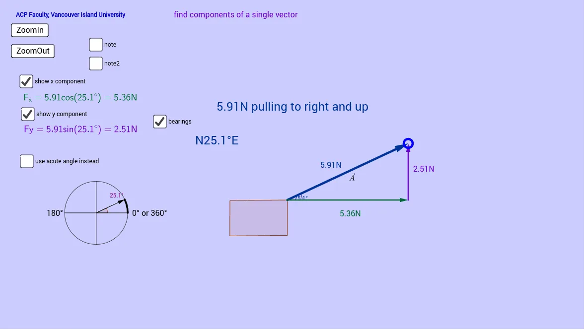
① This example demonstrates how to represent displacement and bearing (direction angle measured clockwise from north) using vectors, with interactive buttons and graphical elements for vector decomposition and composition. ② Core mathematical concepts include vector magnitude and direction, bearing angles, horizontal and vertical components, and geometric construction of polygons (trapezoid). ③ Construction highlights: GeoGebra commands such as Vector, Angle, Distance, Polygon, Segment, Midpoint, Circle, Sector, and Arc are used; objects include vectors a and b, angles angle1/angle2, direction components Hdir/Vdir, and interactive buttons (button1/button2) with text labels. ④ Suitable for high school or early college students learning vector geometry, trigonometry, or bearing applications in navigation, as well as for teachers creating dynamic demonstrations.
GeoGebra Commands & Parameters
Vector(a, b) → AAngle(A) → angle1Distance(a, b) → dAPolygon(a, c, d, e) → poly1, a_1, c_1, d_1, e_1If(x(b) - x(a) > 0, "right", "left") → HdirIf(y(b) - y(a) > 0, "up", "down") → VdirDistance(a, b) → magAVector(a, O) → FiVector(O, b) → FjIf(Hdir ≟ "right" ∧ Vdir ≟ "up", 1, If[Hdir ≟ "left" ∧ Vdir ≟ "up", 2, If[Hdir ≟ "left" ∧ Vdir ≟ "down", 3, 4]]) → quadVector(B, C) → leftAngle(A, left) → angle2Vector(D, E) → rightAngle(A, right) → angle4Angle(left, A) → angle3Segment(F, G) → iMidpoint(i) → oCircle(o, i / 2) → kSegment(H, I) → jCircle(o, 0.5) → unitCVector(o, S) → unitVSector(unitC, G, S) → pArc(k, S, F) → arc2Arc(k, F, S) → arc3Arc(k, G, S) → arc1Arc(k, S, G) → arc4If(quad ≟ 1, angle1, If[quad ≟ 2, angle2, If[quad ≟ 3, angle3, angle4]]) → acuteangle
AI Drawing Prompt Reference
Draw a vector with an arrow from a start point to an end point, labeling its length. From the start point, draw horizontal and vertical reference vectors to decompose the displacement. Based on the end point's direction (right/left, up/down), determine the quadrant and display the corresponding bearing angle (measured clockwise from north). Construct a trapezoid nearby with sides related to the vector direction, and add auxiliary segments, midpoints, circles, and arcs to illustrate angle relationships. Finally, include buttons to switch between bearing angles for different quadrants.
The prompt above was compiled from the original drawing commands and is for reference only.