
Velocity and Force Vector Decomposition (MAT-5173 Task 3)
Loading the math board and drawing, please wait…
In collections
MTH-5173-2-St. Lawrence Seaway
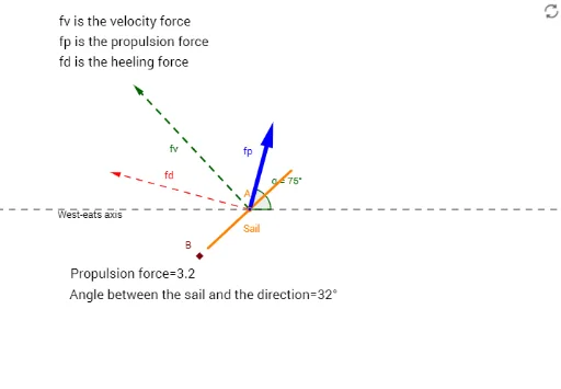
This GeoGebra example demonstrates how to decompose a velocity vector into components along and perpendicular to a sail surface, illustrating the relationship between force, velocity, and angles in a 2D plane. Core mathematical concepts include vector addition and decomposition, orthogonal projection, trigonometric functions (tangent), and angle measurement. The construction uses GeoGebra commands such as Line, Circle, Intersect, Segment, OrthogonalLine, Vector, Rotate, Angle, and Length to build a sail model (object Sail), the velocity vector fv, component forces fd and fp, and multiple auxiliary points (A, B, C, D, E, F, G, H, I) with angles α, β, γ, plus text objects (texte1, texte2, texte3) for numerical labels. It is suitable for high school or introductory college vector lessons, particularly for understanding force decomposition and velocity direction, and can be used in physics mechanics modeling.
GeoGebra Commands & Parameters
Line(A, B) → fCircle(A, 2) → cIntersect(c, f) → C, DSegment(D, C) → SailOrthogonalLine(A, Sail) → gCircle(A, 6) → dIntersect(d, g) → E, FVector(A, F) → fvLine(A, xAxis) → hRotate(G, 75°, A) → G'Angle(G, A, G') → αLine(A, G') → iOrthogonalLine(F, i) → jLine(A, j) → kLine(F, i) → lIntersect(k, l) → HIntersect(i, j) → IVector(A, H) → fdVector(A, I) → fpAngle(h, Sail) → βLength(fp) → FP
AI Drawing Prompt Reference
Draw a 2D diagram showing force decomposition on a sail. Start with a horizontal baseline and a point at its origin. Draw two concentric circles centered at the origin with radii 2 and 6. Use the intersections of the baseline with the inner circle to define the endpoints of a sail segment. Construct a line through the origin perpendicular to the sail, intersecting the outer circle at a point. From the origin to that point, draw a velocity vector. Then draw a ray from the origin making a 75-degree angle with the baseline, and mark that angle. Through the tip of the velocity vector, draw a line perpendicular to this ray, intersecting the ray at one point. Also draw a line through the origin parallel to that perpendicular, and a line through the velocity tip parallel to the ray; their intersection gives another point. From the origin, draw two component vectors to these two intersection points. Finally, label the angle between the baseline and the sail, and indicate the length of one component.
The prompt above was compiled from the original drawing commands and is for reference only.