
Transformational Discovery of Pentagon Interior and Exterior Angle Sums
Loading the math board and drawing, please wait…
In collections
Polyon Interior Angles: Investigations
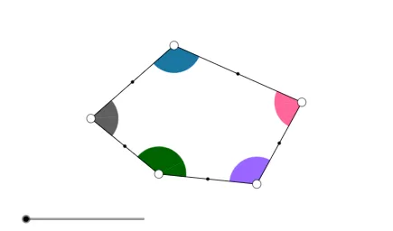
This GeoGebra applet uses a pentagon to guide students to discover the sum of interior angles and the sum of exterior angles through transformational geometry. It focuses on polygon angle concepts—definitions of interior/exterior angles and the corresponding angle-sum invariants—while emphasizing that transformations preserve the relevant angle relationships. Construction-wise, it builds the polygon with Polygon, creates angle-related lines using Line/Ray/Segment, establishes key points with Point and Midpoint, and uses Intersect to determine constructed intersections. It also employs Circle, CircleArc, and CircleSector for arc/circle-based construction, Vector for directed geometric relationships, and transformation commands Translate, Mirror, Rotate, and Dilate to generate and compare angle configurations dynamically (with If for conditional behavior). Suitable for middle and high school geometry lessons, inquiry-based learning, and math enrichment.
GeoGebra Commands & Parameters
Segment(D, E) → i_3Midpoint(i_3) → M_3Ray(A, B) → aRay(B, C) → bRay(C, D) → cRay(D, E) → dRay(E, A) → eCircle(A, 1.5) → fCircle(B, 1.5) → gCircle(C, 1.5) → hCircle(D, 1.5) → kCircle(E, 1.5) → pSegment(C, A) → iSegment(C, E) → jIntersect(f, a, 1) → FIntersect(f, i, 1) → GIntersect(f, e, 1) → HIntersect(f, e, 2) → IIntersect(p, e) → J,Intersect(p, j) → K,Intersect(p, d, 1) → LIntersect(p, d, 2) → MIntersect(k, d, 1) → NIntersect(k, c, 2) → OIntersect(h, c, 1) → PIntersect(h, j, 1) → QIntersect(h, i, 1) → RIntersect(h, b, 1) → SIntersect(g, a, 2) → TIntersect(g, b, 1) → UIntersect(g, a, 1) → VCircleSector(A, F, G) → qCircleSector(A, G, H) → rCircleSector(B, U, V) → sCircleSector(C, P, Q) → tCircleSector(C, Q, R) → c_1CircleSector(C, R, S) → d_1Intersect(k, c, 1) → WCircleSector(D, O, N) → e_1CircleSector(D, N, W) → f_1CircleSector(E, M, J) → g_1CircleSector(E, J, K) → h_1CircleSector(E, K, L) → k_1CircleSector(A, I, F) → p_1CircleSector(B, T, U) → q_1Intersect(h, b, 2) → ZCircleSector(C, Z, P) → r_1Vector(A, B) → uVector(C, B) → vVector(E, D) → wVector(C, D) → u_1Vector(C, E) → v_1Vector(A, E) → w_1Translate(d_1, v) → s_1Mirror(s_1, B) → t_1Dilate(A, If[0 < l ≤ 1, 1 - l, 0], B) → A'Dilate(C, If[0 < l ≤ 1, 1 - l, 0], B) → C'Dilate(A, If[1 < l ≤ 2, 2 - l, 0], E) → A'_1Dilate(C, If[1 < l ≤ 2, 2 - l, 0], E) → C'_1Dilate(C, If[2 < l ≤ 3, 3 - l, 0], D) → C'_2Vector(A, B) → a_1Vector(C, C') → b_1Vector(A, A'_1) → i_1Rotate(E, If[2 < l ≤ 3, ((-(l - 2)) * 180°), (-(180°))], M_3) → E'Vector(E, E') → j_1Vector(C, C'_2) → l_1Vector(C, C'_1) → m_1Translate(d_1, b_1) → c_2Translate(r, i_1) → r'_1Translate(r, w_1) → r'_2Translate(k_1, w) → d_2Translate(k_1, j_1) → e_2Translate(c_1, v_1) → f_2Translate(c_1, m_1) → g_2Translate(t, u_1) → t'Translate(t, l_1) → t'_1Translate(q, a_1) → r'Translate(d_1, b_1) → h_2Vector(A, A') → n_1Line(E, C) → a_2Line(E, D) → b_2Segment(E, C) → i_2Vector(D, C) → u_2Vector(E, C) → v_2Vector(A, C) → w_2Vector(B, C) → l_2Dilate(B, If[0 < o < 1, 1 - o, 0], C) → B'Dilate(A, If[1 < o < 2, 2 - o, 0], C) → A'_2Dilate(E, If[2 < o < 3, 3 - o, 0], C) → E'_1Dilate(D, If[3 < o < 4, 4 - o, 0], C) → D'Vector(B, B') → m_2Vector(A, A'_2) → n_2Vector(E, E'_1) → s_2Vector(D, D') → t_2Translate(q_1, m_2) → c_3Translate(q_1, l_2) → d_3Translate(p_1, w_2) → e_3Translate(g_1, v_2) → f_3Translate(e_1, u_2) → g_3If(1 < o < 2, Translate[p_1, n_2]) → h_3If(2 < o < 3, Translate[g_1, s_2]) → k_3If(3 < o < 4, Translate[e_1, t_2]) → p_3Point(a_2) → A_1Point(a_2) → B_1Ray(C, B_1) → a_3Ray(E, A_1) → b_3Polygon(A, B, C, D, E) → poly1, a_4, b_4, c_4, d_4, e_4Polygon(A, B, C) → poly2, c_5, a_5, b_5Polygon(A, C, E) → poly3, e_5, a_6, c_6Polygon(E, C, D) → poly4, d_5, e_6, c_7Segment(E, A) → j_3Segment(A, B) → l_3Segment(B, C) → m_3Segment(C, D) → n_3Midpoint(j_3) → M_4Midpoint(l_3) → M_5Midpoint(m_3) → M_1Midpoint(n_3) → M_2Rotate(d_1, If[0 < l ≤ 1, ((-l) * 180°), (-(180°))], M_1) → k_2Rotate(C, If[0 < l ≤ 1, ((-l) * 180°), (-(180°))], M_1) → C'_3Segment(M_1, C'_3) → q_3Rotate(q, If[0 < l ≤ 1, (l * 180°), 180°], M_5) → q'Rotate(A, If[0 < l ≤ 1, (l * 180°), 180°], M_5) → A'_3Rotate(R, 180°, M_1) → R'Line(B, R') → s_3Segment(M_5, A'_3) → r_3Rotate(r, If[1 < l ≤ 2, ((-(l - 1)) * 180°), (-(180°))], M_4) → r'_3Rotate(A, If[1 < l ≤ 2, ((-(l - 1)) * 180°), (-(180°))], M_4) → A'_4Segment(M_4, A'_4) → p_2Rotate(t, If[2 < l ≤ 3, ((l - 2) * 180°), 180°], M_2) → t'_2Rotate(C, If[2 < l ≤ 3, ((l - 2) * 180°), 180°], M_2) → C'_4Segment(M_2, C'_4) → q_2Vector(E, D) → j_2Translate(L, j_2) → L'Ray(D, L') → r_2CircleArc(C, R, S) → t_3CircleArc(C, Q, R) → f_4CircleArc(C, P, Q) → g_4CircleArc(A, F, G) → h_4CircleArc(A, G, H) → k_4CircleArc(E, K, L) → p_4Segment(M_3, E') → i_4
AI Drawing Prompt Reference
Draw a pentagon with five vertices. Around each vertex, place a small circle of equal radius. From each vertex, extend rays along the sides of the pentagon, and also draw diagonals connecting some vertices. Use the intersections of these rays with the circles to create multiple circular sectors near each vertex, representing interior and exterior angle regions. Add a vector arrow from one vertex to an adjacent vertex to indicate direction. The final figure combines the pentagon, auxiliary circles, rays, arcs, and a vector, illustrating angle relationships through transformations.
The prompt above was compiled from the original drawing commands and is for reference only.