
Total Internal Reflection
Loading the math board and drawing, please wait…
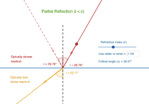
This GeoGebra example dynamically models the phenomenon of total internal reflection, where light traveling through a medium with higher refractive index strikes the boundary with a lower refractive index at an angle exceeding the critical angle, causing complete reflection. Key mathematical concepts include Snell's law, critical angle calculation, ray-optics geometry, and vector-based angle measurement. Construction utilizes GeoGebra commands such as Mirror, Intersect, Ray, Angle, Rotate, Point, Line, and Segment to simulate light paths, reflection interfaces, and angular relationships. The model is suitable for high school physics, optics units, and introductory calculus or geometry courses exploring parametric rays and geometric transformations.
GeoGebra Commands & Parameters
Mirror(B, yAxis) → B'Intersect(xAxis, yAxis) → AMirror(A, yAxis) → A'_1Ray(A'_1, B') → f'Ray(A, B) → fAngle(yAxis, f') → r_{2}Ray(A, C) → gRotate(A, r, (0, 0)) → A'Rotate(C, (-r), (0, 0)) → C'Ray(A', C') → g'Angle(g', g) → r_{1}Ray(A'_1, B') → hPoint(f) → DVector(B, D) → uPoint(f') → GIntersect(r_{2}, f, 1) → HIntersect(f, h) → IPoint(h) → JVector(I, J) → aIntersect(f, h) → LPoint(h) → MVector(L, M) → wIntersect(f, g') → EPoint(g') → FVector(E, F) → vAngle(f, yAxis) → αPoint(yAxis) → KPoint(yAxis) → NPoint(xAxis) → OPoint(xAxis) → PLine(O, P) → jPoint(yAxis) → QPoint(yAxis) → RSegment(Q, R) → iTextfield(n) → InputBox1
AI Drawing Prompt Reference
Create a dynamic model of total internal reflection. Start by placing point B on the y-axis and drawing ray f from the intersection of x-axis and y-axis, point A. Then, place point C on the y-axis and rotate A and C to form ray g. Reflect ray f and g at point B to form f' and g'. Measure the angle α between ray f and the y-axis, and the angle r1 between ray f and g'. Finally, use the intersection points E of ray f and g', and I of ray f and g, to draw vectors v and a, illustrating the path of the rays and the reflection angles.
The prompt above was compiled from the original drawing commands and is for reference only.