
Symmetry Lines and Rotational Symmetry of Regular Polygons
Loading the math board and drawing, please wait…
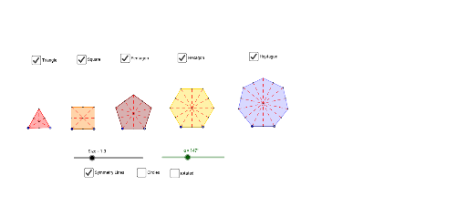
This example demonstrates the relationship between symmetry lines and rotational symmetry in regular polygons. It involves core mathematical concepts such as symmetry, rotational symmetry, and geometric properties of regular polygons. The construction uses GeoGebra commands and objects like Point, Segment, Polygon, LineBisector, Intersect, Rotate, Circle. It is suitable for high school mathematics teaching and geometric learning to visually understand the symmetry characteristics of regular polygons.
GeoGebra Commands & Parameters
Point(Circle[A, Size]) → BSegment(A, B) → bPoint(Circle[C, Size]) → DSegment(C, D) → cPoint(Circle[E, Size]) → FSegment(E, F) → dPoint(Circle[G, Size]) → HSegment(G, H) → ePoint(Circle[I, Size]) → JSegment(I, J) → fPolygon(A, B, 3) → poly1, g, h, i, KPolygon(C, D, 4) → poly2, j, k, l, m, L, MPolygon(E, F, 5) → poly3, n, p, q, r, s, N, O, PPolygon(G, H, 6) → poly4, t, T, a_1, b_1, c_1, d_1, e_1, Q, R, SPolygon(I, J, 7) → poly5, f_1, W, Z, A_1, g_1, h_1, i_1, j_1, k_1, l_1, U, VLineBisector(l) → m_1LineBisector(k) → n_1LineBisector(r) → p_1LineBisector(q) → q_1LineBisector(p) → r_1LineBisector(d) → s_1LineBisector(s) → t_1Intersect(m_1, l) → B_1Intersect(n_1, k) → C_1Intersect(n_1, m) → D_1Intersect(m_1, c) → E_1Segment(B_1, E_1) → a_2Segment(C_1, D_1) → b_2Intersect(a_2, b_2) → F_1Intersect(l, a_2) → G_1Intersect(p_1, r) → H_1Intersect(q_1, q) → I_1Intersect(r_1, p) → J_1Intersect(s_1, d) → K_1Intersect(t_1, s) → L_1Intersect(p_1, q_1) → M_1Segment(F, H_1) → c_2Segment(O, K_1) → d_2Segment(N, L_1) → e_2Segment(P, J_1) → f_2Segment(E, I_1) → g_2LineBisector(j_1) → h_2LineBisector(i_1) → i_2LineBisector(h_1) → j_2LineBisector(g_1) → k_2LineBisector(f) → l_2LineBisector(l_1) → m_2LineBisector(k_1) → n_2Intersect(h_2, j_1) → N_1Intersect(i_2, i_1) → O_1Intersect(j_2, h_1) → P_1Intersect(k_2, g_1) → Q_1Intersect(h_2, i_2) → R_1Intersect(l_2, f) → S_1Intersect(m_2, l_1) → T_1Intersect(n_2, k_1) → U_1Segment(W, S_1) → p_2Segment(Q_1, Z) → q_2Segment(A_1, P_1) → r_2Segment(I, O_1) → s_2Segment(U, U_1) → t_2Segment(J, N_1) → a_3Segment(V, T_1) → b_3LineBisector(c_1) → c_3LineBisector(b_1) → d_3LineBisector(a_1) → e_3LineBisector(h) → f_3LineBisector(i) → g_3LineBisector(b) → h_3Intersect(f_3, h) → V_1Intersect(h_3, b) → W_1Intersect(g_3, i) → Z_1Intersect(e_3, d_1) → A_2Intersect(c_3, c_1) → B_2Intersect(d_3, b_1) → C_2Intersect(e_3, a_1) → D_2Intersect(c_3, e) → E_2Intersect(d_3, e_1) → F_2Intersect(f_3, g_3) → G_2Intersect(c_3, d_3) → H_2Segment(W_1, K) → i_3Segment(B, Z_1) → j_3Segment(A, V_1) → k_3Segment(E_2, B_2) → l_3Segment(F_2, C_2) → m_3Segment(Q, T) → n_3Segment(D_2, A_2) → p_3Segment(H, S) → q_3Segment(G, R) → r_3Rotate(poly1, α, G_2) → poly1'Rotate(poly2, α, F_1) → poly2'Rotate(poly3, α, M_1) → poly3'Rotate(poly4, α, H_2) → poly4'Rotate(poly5, α, R_1) → poly5'Intersect(l, m) → I_2Intersect(k, l) → J_2Segment(D, I_2) → s_3Segment(C, J_2) → t_3Intersect(d_1, p_3) → K_2Intersect(d_1, e_1) → L_2Intersect(r, s) → M_2Intersect(p, q) → N_2Intersect(q, r) → O_2Intersect(c_1, d_1) → P_2Intersect(b_1, c_1) → Q_2Intersect(a_1, b_1) → R_2Intersect(k_1, l_1) → S_2Intersect(j_1, k_1) → T_2Intersect(h_1, i_1) → U_2Intersect(g_1, h_1) → V_2Intersect(h, i) → W_2Circle(G_2, B) → c_4Circle(F_1, D) → d_4Circle(M_1, F) → e_4Circle(H_2, H) → f_4Circle(R_1, J) → g_4
AI Drawing Prompt Reference
Draw regular polygons and their symmetry lines. Start by drawing a regular triangle, then a square, a pentagon, a hexagon, and a heptagon. Find the center of each polygon and draw the symmetry lines through these centers. Finally, connect the intersection points of these symmetry lines to form new segments, which will help illustrate the symmetry of the regular polygons.
The prompt above was compiled from the original drawing commands and is for reference only.